Diagram Scene Example
Demonstrate how to use the Graphics View framework.
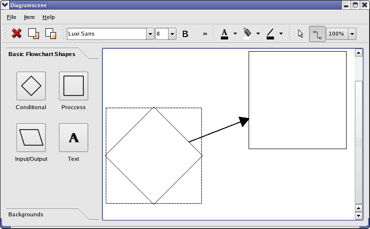
The Diagram Scene example is an application in which you can create a flowchart diagram. It is possible to add flowchart shapes and text and connect the shapes by arrows as shown in the image above. The shapes, arrows, and text can be given different colors, and it is possible to change the font, style, and underline of the text.
The Qt graphics view framework is designed to manage and display custom 2D graphics items. The main classes of the framework are QGraphicsItem, QGraphicsScene and QGraphicsView. The graphics scene manages the items and provides a surface for them. QGraphicsView is a widget that is used to render a scene on the screen. See the Graphics View Framework for a more detailed description of the framework.
In this example we show how to create such custom graphics scenes and items by implementing classes that inherit QGraphicsScene and QGraphicsItem.
In particular we show how to:
- Create custom graphics items.
- Handle mouse events and movement of items.
- Implement a graphics scene that can manage our custom items.
- Custom painting of items.
- Create a movable and editable text item.
The example consists of the following classes:
MainWindowcreates the widgets and display them in a QMainWindow. It also manages the interaction between the widgets and the graphics scene, view and items.DiagramIteminherits QGraphicsPolygonItem and represents a flowchart shape.TextDiagramIteminherits QGraphicsTextItem and represents text items in the diagram. The class adds support for moving the item with the mouse, which is not supported by QGraphicsTextItem.Arrowinherits QGraphicsLineItem and is an arrow that connect two DiagramItems.DiagramSceneinherits QGraphicsDiagramScene and provides support forDiagramItem,ArrowandDiagramTextItem(In addition to the support already handled by QGraphicsScene).
MainWindow Class Definition
class MainWindow : public QMainWindow
{
    Q_OBJECT

public:
   MainWindow();

private slots:
    void backgroundButtonGroupClicked(QAbstractButton *button);
    void buttonGroupClicked(QAbstractButton *button);
    void deleteItem();
    void pointerGroupClicked();
    void bringToFront();
    void sendToBack();
    void itemInserted(DiagramItem *item);
    void textInserted(QGraphicsTextItem *item);
    void currentFontChanged(const QFont &font);
    void fontSizeChanged(const QString &size);
    void sceneScaleChanged(const QString &scale);
    void textColorChanged();
    void itemColorChanged();
    void lineColorChanged();
    void textButtonTriggered();
    void fillButtonTriggered();
    void lineButtonTriggered();
    void handleFontChange();
    void itemSelected(QGraphicsItem *item);
    void about();

private:
    void createToolBox();
    void createActions();
    void createMenus();
    void createToolbars();
    QWidget *createBackgroundCellWidget(const QString &text,
                                        const QString &image);
    QWidget *createCellWidget(const QString &text,
                              DiagramItem::DiagramType type);
    QMenu *createColorMenu(const char *slot, QColor defaultColor);
    QIcon createColorToolButtonIcon(const QString &image, QColor color);
    QIcon createColorIcon(QColor color);

    DiagramScene *scene;
    QGraphicsView *view;

    QAction *exitAction;
    QAction *addAction;
    QAction *deleteAction;

    QAction *toFrontAction;
    QAction *sendBackAction;
    QAction *aboutAction;

    QMenu *fileMenu;
    QMenu *itemMenu;
    QMenu *aboutMenu;

    QToolBar *textToolBar;
    QToolBar *editToolBar;
    QToolBar *colorToolBar;
    QToolBar *pointerToolbar;

    QComboBox *sceneScaleCombo;
    QComboBox *itemColorCombo;
    QComboBox *textColorCombo;
    QComboBox *fontSizeCombo;
    QFontComboBox *fontCombo;

    QToolBox *toolBox;
    QButtonGroup *buttonGroup;
    QButtonGroup *pointerTypeGroup;
    QButtonGroup *backgroundButtonGroup;
    QToolButton *fontColorToolButton;
    QToolButton *fillColorToolButton;
    QToolButton *lineColorToolButton;
    QAction *boldAction;
    QAction *underlineAction;
    QAction *italicAction;
    QAction *textAction;
    QAction *fillAction;
    QAction *lineAction;
};
The MainWindow class creates and lays out the widgets in a QMainWindow. The class forwards input from the widgets to the DiagramScene. It also updates its widgets when the diagram scene's text item changes, or a diagram item or a diagram text item is inserted into the scene.
The class also deletes items from the scene and handles the z-ordering, which decides the order in which items are drawn when they overlap each other.
MainWindow Class Implementation
We start with a look at the constructor:
MainWindow::MainWindow()
{
    createActions();
    createToolBox();
    createMenus();

    scene = new DiagramScene(itemMenu, this);
    scene->setSceneRect(QRectF(0, 0, 5000, 5000));
    connect(scene, &DiagramScene::itemInserted,
            this, &MainWindow::itemInserted);
    connect(scene, &DiagramScene::textInserted,
            this, &MainWindow::textInserted);
    connect(scene, &DiagramScene::itemSelected,
            this, &MainWindow::itemSelected);
    createToolbars();

    QHBoxLayout *layout = new QHBoxLayout;
    layout->addWidget(toolBox);
    view = new QGraphicsView(scene);
    layout->addWidget(view);

    QWidget *widget = new QWidget;
    widget->setLayout(layout);

    setCentralWidget(widget);
    setWindowTitle(tr("Diagramscene"));
    setUnifiedTitleAndToolBarOnMac(true);
}
In the constructor we call methods to create the widgets and layouts of the example before we create the diagram scene. The toolbars must be created after the scene as they connect to its signals. We then lay the widgets out in the window.
We connect to the itemInserted() and textInserted() slots of the diagram scenes as we want to uncheck the buttons in the tool box when an item is inserted. When an item is selected in the scene we receive the itemSelected() signal. We use this to update the widgets that display font properties if the item selected is a DiagramTextItem.
The createToolBox() function creates and lays out the widgets of the toolBox QToolBox. We will not examine it with a high level of detail as it does not deal with graphics framework specific functionality. Here is its implementation:
void MainWindow::createToolBox()
{
    buttonGroup = new QButtonGroup(this);
    buttonGroup->setExclusive(false);
    connect(buttonGroup, QOverload<QAbstractButton *>::of(&QButtonGroup::buttonClicked),
            this, &MainWindow::buttonGroupClicked);
    QGridLayout *layout = new QGridLayout;
    layout->addWidget(createCellWidget(tr("Conditional"), DiagramItem::Conditional), 0, 0);
    layout->addWidget(createCellWidget(tr("Process"), DiagramItem::Step),0, 1);
    layout->addWidget(createCellWidget(tr("Input/Output"), DiagramItem::Io), 1, 0);
This part of the function sets up the tabbed widget item that contains the flowchart shapes. An exclusive QButtonGroup always keeps one button checked; we want the group to allow all buttons to be unchecked. We still use a button group since we can associate user data, which we use to store the diagram type, with each button. The createCellWidget() function sets up the buttons in the tabbed widget item and is examined later.
The buttons of the background tabbed widget item is set up in the same way, so we skip to the creation of the tool box:
    toolBox = new QToolBox;
    toolBox->setSizePolicy(QSizePolicy(QSizePolicy::Maximum, QSizePolicy::Ignored));
    toolBox->setMinimumWidth(itemWidget->sizeHint().width());
    toolBox->addItem(itemWidget, tr("Basic Flowchart Shapes"));
    toolBox->addItem(backgroundWidget, tr("Backgrounds"));
}
We set the preferred size of the toolbox as its maximum. This way, more space is given to the graphics view.
Here is the createActions() function:
void MainWindow::createActions()
{
    toFrontAction = new QAction(QIcon(":/images/bringtofront.png"),
                                tr("Bring to &Front"), this);
    toFrontAction->setShortcut(tr("Ctrl+F"));
    toFrontAction->setStatusTip(tr("Bring item to front"));
    connect(toFrontAction, &QAction::triggered, this, &MainWindow::bringToFront);
We show an example of the creation of an action. The functionality the actions trigger is discussed in the slots we connect the actions to. You can see the application example if you need a high-level introduction to actions.
The is the createMenus() function:
void MainWindow::createMenus()
{
    fileMenu = menuBar()->addMenu(tr("&File"));
    fileMenu->addAction(exitAction);

    itemMenu = menuBar()->addMenu(tr("&Item"));
    itemMenu->addAction(deleteAction);
    itemMenu->addSeparator();
    itemMenu->addAction(toFrontAction);
    itemMenu->addAction(sendBackAction);

    aboutMenu = menuBar()->addMenu(tr("&Help"));
    aboutMenu->addAction(aboutAction);
}
We create the three menus' of the example.
The createToolbars() function sets up the examples tool bars. The three QToolButtons in the colorToolBar, the fontColorToolButton, fillColorToolButton, and lineColorToolButton, are interesting as we create icons for them by drawing on a QPixmap with a QPainter. We show how the fillColorToolButton is created. This button lets the user select a color for the diagram items.
void MainWindow::createToolbars()
{
    ...
    fillColorToolButton = new QToolButton;
    fillColorToolButton->setPopupMode(QToolButton::MenuButtonPopup);
    fillColorToolButton->setMenu(createColorMenu(SLOT(itemColorChanged()), Qt::white));
    fillAction = fillColorToolButton->menu()->defaultAction();
    fillColorToolButton->setIcon(createColorToolButtonIcon(
                                     ":/images/floodfill.png", Qt::white));
    connect(fillColorToolButton, &QAbstractButton::clicked,
            this, &MainWindow::fillButtonTriggered);
We set the menu of the tool button with setMenu(). We need the fillAction QAction object to always be pointing to the selected action of the menu. The menu is created with the createColorMenu() function and, as we shall see later, contains one menu item for each color that the items can have. When the user presses the button, which trigger the clicked() signal, we can set the color of the selected item to the color of fillAction. It is with createColorToolButtonIcon() we create the icon for the button.
    ...
}
Here is the createBackgroundCellWidget() function:
QWidget *MainWindow::createBackgroundCellWidget(const QString &text, const QString &image)
{
    QToolButton *button = new QToolButton;
    button->setText(text);
    button->setIcon(QIcon(image));
    button->setIconSize(QSize(50, 50));
    button->setCheckable(true);
    backgroundButtonGroup->addButton(button);

    QGridLayout *layout = new QGridLayout;
    layout->addWidget(button, 0, 0, Qt::AlignHCenter);
    layout->addWidget(new QLabel(text), 1, 0, Qt::AlignCenter);

    QWidget *widget = new QWidget;
    widget->setLayout(layout);

    return widget;
}
This function creates QWidgets containing a tool button and a label. The widgets created with this function are used for the background tabbed widget item in the tool box.
Here is the createCellWidget() function:
QWidget *MainWindow::createCellWidget(const QString &text, DiagramItem::DiagramType type)
{

    DiagramItem item(type, itemMenu);
    QIcon icon(item.image());

    QToolButton *button = new QToolButton;
    button->setIcon(icon);
    button->setIconSize(QSize(50, 50));
    button->setCheckable(true);
    buttonGroup->addButton(button, int(type));

    QGridLayout *layout = new QGridLayout;
    layout->addWidget(button, 0, 0, Qt::AlignHCenter);
    layout->addWidget(new QLabel(text), 1, 0, Qt::AlignCenter);

    QWidget *widget = new QWidget;
    widget->setLayout(layout);

    return widget;
}
This function returns a QWidget containing a QToolButton with an image of one of the DiagramItems, i.e., flowchart shapes. The image is created by the DiagramItem through the image() function. The QButtonGroup class lets us attach an id (int) with each button; we store the diagram's type, i.e., the DiagramItem::DiagramType enum. We use the stored diagram type when we create new diagram items for the scene. The widgets created with this function is used in the tool box.
Here is the createColorMenu() function:
QMenu *MainWindow::createColorMenu(const char *slot, QColor defaultColor)
{
    QList<QColor> colors;
    colors << Qt::black << Qt::white << Qt::red << Qt::blue << Qt::yellow;
    QStringList names;
    names << tr("black") << tr("white") << tr("red") << tr("blue")
          << tr("yellow");

    QMenu *colorMenu = new QMenu(this);
    for (int i = 0; i < colors.count(); ++i) {
        QAction *action = new QAction(names.at(i), this);
        action->setData(colors.at(i));
        action->setIcon(createColorIcon(colors.at(i)));
        connect(action, SIGNAL(triggered()), this, slot);
        colorMenu->addAction(action);
        if (colors.at(i) == defaultColor)
            colorMenu->setDefaultAction(action);
    }
    return colorMenu;
}
This function creates a color menu that is used as the drop-down menu for the tool buttons in the colorToolBar. We create an action for each color that we add to the menu. We fetch the actions data when we set the color of items, lines, and text.
Here is the createColorToolButtonIcon() function:
QIcon MainWindow::createColorToolButtonIcon(const QString &imageFile, QColor color)
{
    QPixmap pixmap(50, 80);
    pixmap.fill(Qt::transparent);
    QPainter painter(&pixmap);
    QPixmap image(imageFile);
    // Draw icon centred horizontally on button.
    QRect target(4, 0, 42, 43);
    QRect source(0, 0, 42, 43);
    painter.fillRect(QRect(0, 60, 50, 80), color);
    painter.drawPixmap(target, image, source);

    return QIcon(pixmap);
}
This function is used to create the QIcon of the fillColorToolButton, fontColorToolButton, and lineColorToolButton. The imageFile string is either the text, flood-fill, or line symbol that is used for the buttons. Beneath the image we draw a filled rectangle using color.
Here is the createColorIcon() function:
QIcon MainWindow::createColorIcon(QColor color)
{
    QPixmap pixmap(20, 20);
    QPainter painter(&pixmap);
    painter.setPen(Qt::NoPen);
    painter.fillRect(QRect(0, 0, 20, 20), color);

    return QIcon(pixmap);
}
This function creates an icon with a filled rectangle in the color of color. It is used for creating icons for the color menus in the fillColorToolButton, fontColorToolButton, and lineColorToolButton.
Here is the backgroundButtonGroupClicked() slot:
void MainWindow::backgroundButtonGroupClicked(QAbstractButton *button)
{
    const QList<QAbstractButton *> buttons = backgroundButtonGroup->buttons();
    for (QAbstractButton *myButton : buttons) {
        if (myButton != button)
            button->setChecked(false);
    }
    QString text = button->text();
    if (text == tr("Blue Grid"))
        scene->setBackgroundBrush(QPixmap(":/images/background1.png"));
    else if (text == tr("White Grid"))
        scene->setBackgroundBrush(QPixmap(":/images/background2.png"));
    else if (text == tr("Gray Grid"))
        scene->setBackgroundBrush(QPixmap(":/images/background3.png"));
    else
        scene->setBackgroundBrush(QPixmap(":/images/background4.png"));

    scene->update();
    view->update();
}
In this function we set the QBrush that is used to draw the background of the diagramscene. The background can be a grid of squares of blue, gray, or white tiles, or no grid at all. We have QPixmaps of the tiles from png files that we create the brush with.
When one of the buttons in the background tabbed widget item is clicked we change the brush; we find out which button it is by checking its text.
Here is the implementation of buttonGroupClicked():
void MainWindow::buttonGroupClicked(QAbstractButton *button)
{
    const QList<QAbstractButton *> buttons = buttonGroup->buttons();
    for (QAbstractButton *myButton : buttons) {
        if (myButton != button)
            button->setChecked(false);
    }
    const int id = buttonGroup->id(button);
    if (id == InsertTextButton) {
        scene->setMode(DiagramScene::InsertText);
    } else {
        scene->setItemType(DiagramItem::DiagramType(id));
        scene->setMode(DiagramScene::InsertItem);
    }
}
This slot is called when a button in buttonGroup is checked. When a button is checked the user can click on the graphics view and a DiagramItem of the selected type will be inserted into the DiagramScene. We must loop through the buttons in the group to uncheck other buttons as only one button is allowed to be checked at a time.
QButtonGroup assigns an id to each button. We have set the id of each button to the diagram type, as given by DiagramItem::DiagramType that will be inserted into the scene when it is clicked. We can then use the button id when we set the diagram type with setItemType(). In the case of text we assigned an id that has a value that is not in the DiagramType enum.
Here is the implementation of deleteItem():
void MainWindow::deleteItem()
{
    QList<QGraphicsItem *> selectedItems = scene->selectedItems();
    for (QGraphicsItem *item : qAsConst(selectedItems)) {
        if (item->type() == Arrow::Type) {
            scene->removeItem(item);
            Arrow *arrow = qgraphicsitem_cast<Arrow *>(item);
            arrow->startItem()->removeArrow(arrow);
            arrow->endItem()->removeArrow(arrow);
            delete item;
        }
    }

    selectedItems = scene->selectedItems();
    for (QGraphicsItem *item : qAsConst(selectedItems)) {
         if (item->type() == DiagramItem::Type)
             qgraphicsitem_cast<DiagramItem *>(item)->removeArrows();
         scene->removeItem(item);
         delete item;
     }
}
This slot deletes the selected item, if any, from the scene. It deletes the arrows first in order to avoid to delete them twice. If the item to be deleted is a DiagramItem, we also need to delete arrows connected to it; we don't want arrows in the scene that aren't connected to items in both ends.
This is the implementation of pointerGroupClicked():
void MainWindow::pointerGroupClicked()
{
    scene->setMode(DiagramScene::Mode(pointerTypeGroup->checkedId()));
}
The pointerTypeGroup decides whether the scene is in ItemMove or InsertLine mode. This button group is exclusive, i.e., only one button is checked at any time. As with the buttonGroup above we have assigned an id to the buttons that matches values of the DiagramScene::Mode enum, so that we can use the id to set the correct mode.
Here is the bringToFront() slot:
void MainWindow::bringToFront()
{
    if (scene->selectedItems().isEmpty())
        return;

    QGraphicsItem *selectedItem = scene->selectedItems().first();
    const QList<QGraphicsItem *> overlapItems = selectedItem->collidingItems();

    qreal zValue = 0;
    for (const QGraphicsItem *item : overlapItems) {
        if (item->zValue() >= zValue && item->type() == DiagramItem::Type)
            zValue = item->zValue() + 0.1;
    }
    selectedItem->setZValue(zValue);
}
Several items may collide, i.e., overlap, with each other in the scene. This slot is called when the user requests that an item should be placed on top of the items it collides with. QGrapicsItems have a z-value that decides the order in which items are stacked in the scene; you can think of it as the z-axis in a 3D coordinate system. When items collide the items with higher z-values will be drawn on top of items with lower values. When we bring an item to the front we can loop through the items it collides with and set a z-value that is higher than all of them.
Here is the sendToBack() slot:
void MainWindow::sendToBack()
{
    if (scene->selectedItems().isEmpty())
        return;

    QGraphicsItem *selectedItem = scene->selectedItems().first();
    const QList<QGraphicsItem *> overlapItems = selectedItem->collidingItems();

    qreal zValue = 0;
    for (const QGraphicsItem *item : overlapItems) {
        if (item->zValue() <= zValue && item->type() == DiagramItem::Type)
            zValue = item->zValue() - 0.1;
    }
    selectedItem->setZValue(zValue);
}
This slot works in the same way as bringToFront() described above, but sets a z-value that is lower than items the item that should be send to the back collides with.
This is the implementation of itemInserted():
void MainWindow::itemInserted(DiagramItem *item)
{
    pointerTypeGroup->button(int(DiagramScene::MoveItem))->setChecked(true);
    scene->setMode(DiagramScene::Mode(pointerTypeGroup->checkedId()));
    buttonGroup->button(int(item->diagramType()))->setChecked(false);
}
This slot is called from the DiagramScene when an item has been added to the scene. We set the mode of the scene back to the mode before the item was inserted, which is ItemMove or InsertText depending on which button is checked in the pointerTypeGroup. We must also uncheck the button in the in the buttonGroup.
Here is the implementation of textInserted():
void MainWindow::textInserted(QGraphicsTextItem *)
{
    buttonGroup->button(InsertTextButton)->setChecked(false);
    scene->setMode(DiagramScene::Mode(pointerTypeGroup->checkedId()));
}
We simply set the mode of the scene back to the mode it had before the text was inserted.
Here is the currentFontChanged() slot:
void MainWindow::currentFontChanged(const QFont &)
{
    handleFontChange();
}
When the user requests a font change, by using one of the widgets in the fontToolBar, we create a new QFont object and set its properties to match the state of the widgets. This is done in handleFontChange(), so we simply call that slot.
Here is the fontSizeChanged() slot:
void MainWindow::fontSizeChanged(const QString &)
{
    handleFontChange();
}
When the user requests a font change, by using one of the widgets in the fontToolBar, we create a new QFont object and set its properties to match the state of the widgets. This is done in handleFontChange(), so we simply call that slot.
Here is the implementation of sceneScaleChanged():
void MainWindow::sceneScaleChanged(const QString &scale)
{
    double newScale = scale.left(scale.indexOf(tr("%"))).toDouble() / 100.0;
    QTransform oldMatrix = view->transform();
    view->resetTransform();
    view->translate(oldMatrix.dx(), oldMatrix.dy());
    view->scale(newScale, newScale);
}
The user can increase or decrease the scale, with the sceneScaleCombo, the scene is drawn in. It is not the scene itself that changes its scale, but only the view.
Here is the textColorChanged() slot:
void MainWindow::textColorChanged()
{
    textAction = qobject_cast<QAction *>(sender());
    fontColorToolButton->setIcon(createColorToolButtonIcon(
                                     ":/images/textpointer.png",
                                     qvariant_cast<QColor>(textAction->data())));
    textButtonTriggered();
}
This slot is called when an item in the drop-down menu of the fontColorToolButton is pressed. We need to change the icon on the button to the color of the selected QAction. We keep a pointer to the selected action in textAction. It is in textButtonTriggered() we change the text color to the color of textAction, so we call that slot.
Here is the itemColorChanged() implementation:
void MainWindow::itemColorChanged()
{
    fillAction = qobject_cast<QAction *>(sender());
    fillColorToolButton->setIcon(createColorToolButtonIcon(
                                     ":/images/floodfill.png",
                                     qvariant_cast<QColor>(fillAction->data())));
    fillButtonTriggered();
}
This slot handles requests for changing the color of DiagramItems in the same manner as textColorChanged() does for DiagramTextItems.
Here is the implementation of lineColorChanged():
void MainWindow::lineColorChanged()
{
    lineAction = qobject_cast<QAction *>(sender());
    lineColorToolButton->setIcon(createColorToolButtonIcon(
                                     ":/images/linecolor.png",
                                     qvariant_cast<QColor>(lineAction->data())));
    lineButtonTriggered();
}
This slot handles requests for changing the color of Arrows in the same manner that textColorChanged() does it for DiagramTextItems.
Here is the textButtonTriggered() slot:
void MainWindow::textButtonTriggered()
{
    scene->setTextColor(qvariant_cast<QColor>(textAction->data()));
}
textAction points to the QAction of the currently selected menu item in the fontColorToolButton's color drop-down menu. We have set the data of the action to the QColor the action represents, so we can simply fetch this when we set the color of text with setTextColor().
Here is the fillButtonTriggered() slot:
void MainWindow::fillButtonTriggered()
{
    scene->setItemColor(qvariant_cast<QColor>(fillAction->data()));
}
fillAction points to the selected menu item in the drop-down menu of fillColorToolButton(). We can therefore use the data of this action when we set the item color with setItemColor().
Here is the lineButtonTriggered() slot:
void MainWindow::lineButtonTriggered()
{
    scene->setLineColor(qvariant_cast<QColor>(lineAction->data()));
}
lineAction point to the selected item in the drop-down menu of lineColorToolButton. We use its data when we set the arrow color with setLineColor().
Here is the handleFontChange() function:
void MainWindow::handleFontChange()
{
    QFont font = fontCombo->currentFont();
    font.setPointSize(fontSizeCombo->currentText().toInt());
    font.setWeight(boldAction->isChecked() ? QFont::Bold : QFont::Normal);
    font.setItalic(italicAction->isChecked());
    font.setUnderline(underlineAction->isChecked());

    scene->setFont(font);
}
handleFontChange() is called when any of the widgets that show font properties changes. We create a new QFont object and set its properties based on the widgets. We then call the setFont() function of DiagramScene; it is the scene that set the font of the DiagramTextItems it manages.
Here is the itemSelected() slot:
void MainWindow::itemSelected(QGraphicsItem *item)
{
    DiagramTextItem *textItem =
    qgraphicsitem_cast<DiagramTextItem *>(item);

    QFont font = textItem->font();
    fontCombo->setCurrentFont(font);
    fontSizeCombo->setEditText(QString().setNum(font.pointSize()));
    boldAction->setChecked(font.weight() == QFont::Bold);
    italicAction->setChecked(font.italic());
    underlineAction->setChecked(font.underline());
}
This slot is called when an item in the DiagramScene is selected. In the case of this example it is only text items that emit signals when they are selected, so we do not need to check what kind of graphics item is.
We set the state of the widgets to match the properties of the font of the selected text item.
This is the about() slot:
void MainWindow::about()
{
    QMessageBox::about(this, tr("About Diagram Scene"),
                       tr("The <b>Diagram Scene</b> example shows "
                          "use of the graphics framework."));
}
This slot displays an about box for the example when the user selects the about menu item from the help menu.
DiagramScene Class Definition
The DiagramScene class inherits QGraphicsScene and adds functionality to handle DiagramItems, Arrows, and DiagramTextItems in addition to the items handled by its super class.
class DiagramScene : public QGraphicsScene
{
    Q_OBJECT

public:
    enum Mode { InsertItem, InsertLine, InsertText, MoveItem };

    explicit DiagramScene(QMenu *itemMenu, QObject *parent = nullptr);
    QFont font() const { return myFont; }
    QColor textColor() const { return myTextColor; }
    QColor itemColor() const { return myItemColor; }
    QColor lineColor() const { return myLineColor; }
    void setLineColor(const QColor &color);
    void setTextColor(const QColor &color);
    void setItemColor(const QColor &color);
    void setFont(const QFont &font);

public slots:
    void setMode(Mode mode);
    void setItemType(DiagramItem::DiagramType type);
    void editorLostFocus(DiagramTextItem *item);

signals:
    void itemInserted(DiagramItem *item);
    void textInserted(QGraphicsTextItem *item);
    void itemSelected(QGraphicsItem *item);

protected:
    void mousePressEvent(QGraphicsSceneMouseEvent *mouseEvent) override;
    void mouseMoveEvent(QGraphicsSceneMouseEvent *mouseEvent) override;
    void mouseReleaseEvent(QGraphicsSceneMouseEvent *mouseEvent) override;

private:
    bool isItemChange(int type) const;

    DiagramItem::DiagramType myItemType;
    QMenu *myItemMenu;
    Mode myMode;
    bool leftButtonDown;
    QPointF startPoint;
    QGraphicsLineItem *line;
    QFont myFont;
    DiagramTextItem *textItem;
    QColor myTextColor;
    QColor myItemColor;
    QColor myLineColor;
};
In the DiagramScene a mouse click can give three different actions: the item under the mouse can be moved, an item may be inserted, or an arrow may be connected between to diagram items. Which action a mouse click has depends on the mode, given by the Mode enum, the scene is in. The mode is set with the setMode() function.
The scene also sets the color of its items and the font of its text items. The colors and font used by the scene can be set with the setLineColor(), setTextColor(), setItemColor() and setFont() functions. The type of DiagramItem, given by the DiagramItem::DiagramType function, to be created when an item is inserted is set with the setItemType() slot.
The MainWindow and DiagramScene share responsibility for the examples functionality. MainWindow handles the following tasks: the deletion of items, text, and arrows; moving diagram items to the back and front; and setting the scale of the scene.
DiagramScene Class Implementation
We start with the constructor:
DiagramScene::DiagramScene(QMenu *itemMenu, QObject *parent)
    : QGraphicsScene(parent)
{
    myItemMenu = itemMenu;
    myMode = MoveItem;
    myItemType = DiagramItem::Step;
    line = nullptr;
    textItem = nullptr;
    myItemColor = Qt::white;
    myTextColor = Qt::black;
    myLineColor = Qt::black;
}
The scene uses myItemMenu to set the context menu when it creates DiagramItems. We set the default mode to DiagramScene::MoveItem as this gives the default behavior of QGraphicsScene.
Here is the setLineColor() function:
void DiagramScene::setLineColor(const QColor &color)
{
    myLineColor = color;
    if (isItemChange(Arrow::Type)) {
        Arrow *item = qgraphicsitem_cast<Arrow *>(selectedItems().first());
        item->setColor(myLineColor);
        update();
    }
}
The isItemChange function returns true if an Arrow item is selected in the scene in which case we want to change its color. When the DiagramScene creates and adds new arrows to the scene it will also use the new color.
Here is the setTextColor() function:
void DiagramScene::setTextColor(const QColor &color)
{
    myTextColor = color;
    if (isItemChange(DiagramTextItem::Type)) {
        DiagramTextItem *item = qgraphicsitem_cast<DiagramTextItem *>(selectedItems().first());
        item->setDefaultTextColor(myTextColor);
    }
}
This function sets the color of DiagramTextItems equal to the way setLineColor() sets the color of Arrows.
Here is the setItemColor() function:
void DiagramScene::setItemColor(const QColor &color)
{
    myItemColor = color;
    if (isItemChange(DiagramItem::Type)) {
        DiagramItem *item = qgraphicsitem_cast<DiagramItem *>(selectedItems().first());
        item->setBrush(myItemColor);
    }
}
This function sets the color the scene will use when creating DiagramItems. It also changes the color of a selected DiagramItem.
This is the implementation of setFont():
void DiagramScene::setFont(const QFont &font)
{
    myFont = font;

    if (isItemChange(DiagramTextItem::Type)) {
        QGraphicsTextItem *item = qgraphicsitem_cast<DiagramTextItem *>(selectedItems().first());
        //At this point the selection can change so the first selected item might not be a DiagramTextItem
        if (item)
            item->setFont(myFont);
    }
}
Set the font to use for new and selected, if a text item is selected, DiagramTextItems.
This is the implementation of editorLostFocus() slot:
void DiagramScene::editorLostFocus(DiagramTextItem *item)
{
    QTextCursor cursor = item->textCursor();
    cursor.clearSelection();
    item->setTextCursor(cursor);

    if (item->toPlainText().isEmpty()) {
        removeItem(item);
        item->deleteLater();
    }
}
DiagramTextItems emit a signal when they lose focus, which is connected to this slot. We remove the item if it has no text. If not, we would leak memory and confuse the user as the items will be edited when pressed on by the mouse.
The mousePressEvent() function handles mouse press event's different depending on which mode the DiagramScene is in. We examine its implementation for each mode:
void DiagramScene::mousePressEvent(QGraphicsSceneMouseEvent *mouseEvent)
{
    if (mouseEvent->button() != Qt::LeftButton)
        return;

    DiagramItem *item;
    switch (myMode) {
        case InsertItem:
            item = new DiagramItem(myItemType, myItemMenu);
            item->setBrush(myItemColor);
            addItem(item);
            item->setPos(mouseEvent->scenePos());
            emit itemInserted(item);
            break;
We simply create a new DiagramItem and add it to the scene at the position the mouse was pressed. Note that the origin of its local coordinate system will be under the mouse pointer position.
        case InsertLine:
            line = new QGraphicsLineItem(QLineF(mouseEvent->scenePos(),
                                        mouseEvent->scenePos()));
            line->setPen(QPen(myLineColor, 2));
            addItem(line);
            break;
The user adds Arrows to the scene by stretching a line between the items the arrow should connect. The start of the line is fixed in the place the user clicked the mouse and the end follows the mouse pointer as long as the button is held down. When the user releases the mouse button an Arrow will be added to the scene if there is a DiagramItem under the start and end of the line. We will see how this is implemented later; here we simply add the line.
        case InsertText:
            textItem = new DiagramTextItem();
            textItem->setFont(myFont);
            textItem->setTextInteractionFlags(Qt::TextEditorInteraction);
            textItem->setZValue(1000.0);
            connect(textItem, &DiagramTextItem::lostFocus,
                    this, &DiagramScene::editorLostFocus);
            connect(textItem, &DiagramTextItem::selectedChange,
                    this, &DiagramScene::itemSelected);
            addItem(textItem);
            textItem->setDefaultTextColor(myTextColor);
            textItem->setPos(mouseEvent->scenePos());
            emit textInserted(textItem);
The DiagramTextItem is editable when the Qt::TextEditorInteraction flag is set, else it is movable by the mouse. We always want the text to be drawn on top of the other items in the scene, so we set the value to a number higher than other items in the scene.
    default:
        ;
    }
    QGraphicsScene::mousePressEvent(mouseEvent);
}
We are in MoveItem mode if we get to the default switch; we can then call the QGraphicsScene implementation, which handles movement of items with the mouse. We make this call even if we are in another mode making it possible to add an item and then keep the mouse button pressed down and start moving the item. In the case of text items, this is not possible as they do not propagate mouse events when they are editable.
This is the mouseMoveEvent() function:
void DiagramScene::mouseMoveEvent(QGraphicsSceneMouseEvent *mouseEvent)
{
    if (myMode == InsertLine && line != nullptr) {
        QLineF newLine(line->line().p1(), mouseEvent->scenePos());
        line->setLine(newLine);
    } else if (myMode == MoveItem) {
        QGraphicsScene::mouseMoveEvent(mouseEvent);
    }
}
We must draw the line if we are in InsertMode and the mouse button is pressed down (the line is not 0). As discussed in mousePressEvent() the line is drawn from the position the mouse was pressed to the current position of the mouse.
If we are in MoveItem mode, we call the QGraphicsScene implementation, which handles movement of items.
In the mouseReleaseEvent() function we need to check if an arrow should be added to the scene:
void DiagramScene::mouseReleaseEvent(QGraphicsSceneMouseEvent *mouseEvent)
{
    if (line != nullptr && myMode == InsertLine) {
        QList<QGraphicsItem *> startItems = items(line->line().p1());
        if (startItems.count() && startItems.first() == line)
            startItems.removeFirst();
        QList<QGraphicsItem *> endItems = items(line->line().p2());
        if (endItems.count() && endItems.first() == line)
            endItems.removeFirst();

        removeItem(line);
        delete line;
First we need to get the items (if any) under the line's start and end points. The line itself is the first item at these points, so we remove it from the lists. As a precaution, we check if the lists are empty, but this should never happen.
        if (startItems.count() > 0 && endItems.count() > 0 &&
            startItems.first()->type() == DiagramItem::Type &&
            endItems.first()->type() == DiagramItem::Type &&
            startItems.first() != endItems.first()) {
            DiagramItem *startItem = qgraphicsitem_cast<DiagramItem *>(startItems.first());
            DiagramItem *endItem = qgraphicsitem_cast<DiagramItem *>(endItems.first());
            Arrow *arrow = new Arrow(startItem, endItem);
            arrow->setColor(myLineColor);
            startItem->addArrow(arrow);
            endItem->addArrow(arrow);
            arrow->setZValue(-1000.0);
            addItem(arrow);
            arrow->updatePosition();
        }
    }
Now we check if there are two different DiagramItems under the lines start and end points. If there are we can create an Arrow with the two items. The arrow is then added to each item and finally the scene. The arrow must be updated to adjust its start and end points to the items. We set the z-value of the arrow to -1000.0 because we always want it to be drawn under the items.
    line = nullptr;
    QGraphicsScene::mouseReleaseEvent(mouseEvent);
}
Here is the isItemChange() function:
bool DiagramScene::isItemChange(int type) const
{
    const QList<QGraphicsItem *> items = selectedItems();
    const auto cb = [type](const QGraphicsItem *item) { return item->type() == type; };
    return std::find_if(items.begin(), items.end(), cb) != items.end();
}
The scene has single selection, i.e., only one item can be selected at any given time. The for loop will then loop one time with the selected item or none if no item is selected. isItemChange() is used to check whether a selected item exists and also is of the specified diagram type.
DiagramItem Class Definition
class DiagramItem : public QGraphicsPolygonItem
{
public:
    enum { Type = UserType + 15 };
    enum DiagramType { Step, Conditional, StartEnd, Io };

    DiagramItem(DiagramType diagramType, QMenu *contextMenu, QGraphicsItem *parent = nullptr);

    void removeArrow(Arrow *arrow);
    void removeArrows();
    DiagramType diagramType() const { return myDiagramType; }
    QPolygonF polygon() const { return myPolygon; }
    void addArrow(Arrow *arrow);
    QPixmap image() const;
    int type() const override { return Type; }

protected:
    void contextMenuEvent(QGraphicsSceneContextMenuEvent *event) override;
    QVariant itemChange(GraphicsItemChange change, const QVariant &value) override;

private:
    DiagramType myDiagramType;
    QPolygonF myPolygon;
    QMenu *myContextMenu;
    QVector<Arrow *> arrows;
};
The DiagramItem represents a flowchart shape in the DiagramScene. It inherits QGraphicsPolygonItem and has a polygon for each shape. The enum DiagramType has a value for each of the flowchart shapes.
The class has a list of the arrows that are connected to it. This is necessary because only the item knows when it is being moved (with the itemChanged() function) at which time the arrows must be updated. The item can also draw itself onto a QPixmap with the image() function. This is used for the tool buttons in MainWindow, see createColorToolButtonIcon() in MainWindow.
The Type enum is a unique identifier of the class. It is used by qgraphicsitem_cast(), which does dynamic casts of graphics items. The UserType constant is the minimum value a custom graphics item type can be.
DiagramItem Class Implementation
We start with a look at the constructor:
DiagramItem::DiagramItem(DiagramType diagramType, QMenu *contextMenu,
                         QGraphicsItem *parent)
    : QGraphicsPolygonItem(parent), myDiagramType(diagramType)
    , myContextMenu(contextMenu)
{
    QPainterPath path;
    switch (myDiagramType) {
        case StartEnd:
            path.moveTo(200, 50);
            path.arcTo(150, 0, 50, 50, 0, 90);
            path.arcTo(50, 0, 50, 50, 90, 90);
            path.arcTo(50, 50, 50, 50, 180, 90);
            path.arcTo(150, 50, 50, 50, 270, 90);
            path.lineTo(200, 25);
            myPolygon = path.toFillPolygon();
            break;
        case Conditional:
            myPolygon << QPointF(-100, 0) << QPointF(0, 100)
                      << QPointF(100, 0) << QPointF(0, -100)
                      << QPointF(-100, 0);
            break;
        case Step:
            myPolygon << QPointF(-100, -100) << QPointF(100, -100)
                      << QPointF(100, 100) << QPointF(-100, 100)
                      << QPointF(-100, -100);
            break;
        default:
            myPolygon << QPointF(-120, -80) << QPointF(-70, 80)
                      << QPointF(120, 80) << QPointF(70, -80)
                      << QPointF(-120, -80);
            break;
    }
    setPolygon(myPolygon);
    setFlag(QGraphicsItem::ItemIsMovable, true);
    setFlag(QGraphicsItem::ItemIsSelectable, true);
    setFlag(QGraphicsItem::ItemSendsGeometryChanges, true);
}
In the constructor we create the items polygon according to diagramType. QGraphicsItems are not movable or selectable by default, so we must set these properties.
Here is the removeArrow() function:
void DiagramItem::removeArrow(Arrow *arrow)
{
    arrows.removeAll(arrow);
}
removeArrow() is used to remove Arrow items when they or DiagramItems they are connected to are removed from the scene.
Here is the removeArrows() function:
void DiagramItem::removeArrows()
{
    // need a copy here since removeArrow() will
    // modify the arrows container
    const auto arrowsCopy = arrows;
    for (Arrow *arrow : arrowsCopy) {
        arrow->startItem()->removeArrow(arrow);
        arrow->endItem()->removeArrow(arrow);
        scene()->removeItem(arrow);
        delete arrow;
    }
}
This function is called when the item is removed from the scene and removes all arrows that are connected to this item. The arrow must be removed from the arrows list of both its start and end item. Since either the start or the end item is the object where this function is currently called, we have to make sure to work on a copy of arrows since removeArrow() is modifying this container.
Here is the addArrow() function:
void DiagramItem::addArrow(Arrow *arrow)
{
    arrows.append(arrow);
}
This function simply adds the arrow to the items arrows list.
Here is the image() function:
QPixmap DiagramItem::image() const
{
    QPixmap pixmap(250, 250);
    pixmap.fill(Qt::transparent);
    QPainter painter(&pixmap);
    painter.setPen(QPen(Qt::black, 8));
    painter.translate(125, 125);
    painter.drawPolyline(myPolygon);

    return pixmap;
}
This function draws the polygon of the item onto a QPixmap. In this example we use this to create icons for the tool buttons in the tool box.
Here is the contextMenuEvent() function:
void DiagramItem::contextMenuEvent(QGraphicsSceneContextMenuEvent *event)
{
    scene()->clearSelection();
    setSelected(true);
    myContextMenu->exec(event->screenPos());
}
We show the context menu. As right mouse clicks, which shows the menu, don't select items by default we set the item selected with setSelected(). This is necessary since an item must be selected to change its elevation with the bringToFront and sendToBack actions.
This is the implementation of itemChange():
QVariant DiagramItem::itemChange(GraphicsItemChange change, const QVariant &value)
{
    if (change == QGraphicsItem::ItemPositionChange) {
        for (Arrow *arrow : qAsConst(arrows))
            arrow->updatePosition();
    }

    return value;
}
If the item has moved, we need to update the positions of the arrows connected to it. The implementation of QGraphicsItem does nothing, so we just return value.
DiagramTextItem Class Definition
The TextDiagramItem class inherits QGraphicsTextItem and adds the possibility to move editable text items. Editable QGraphicsTextItems are designed to be fixed in place and editing starts when the user single clicks on the item. With DiagramTextItem the editing starts with a double click leaving single click available to interact with and move it.
class DiagramTextItem : public QGraphicsTextItem
{
    Q_OBJECT

public:
    enum { Type = UserType + 3 };

    DiagramTextItem(QGraphicsItem *parent = nullptr);

    int type() const override { return Type; }

signals:
    void lostFocus(DiagramTextItem *item);
    void selectedChange(QGraphicsItem *item);

protected:
    QVariant itemChange(GraphicsItemChange change, const QVariant &value) override;
    void focusOutEvent(QFocusEvent *event) override;
    void mouseDoubleClickEvent(QGraphicsSceneMouseEvent *event) override;
};
We use itemChange() and focusOutEvent() to notify the DiagramScene when the text item loses focus and gets selected.
We reimplement the functions that handle mouse events to make it possible to alter the mouse behavior of QGraphicsTextItem.
DiagramTextItem Implementation
We start with the constructor:
DiagramTextItem::DiagramTextItem(QGraphicsItem *parent)
    : QGraphicsTextItem(parent)
{
    setFlag(QGraphicsItem::ItemIsMovable);
    setFlag(QGraphicsItem::ItemIsSelectable);
}
We simply set the item movable and selectable, as these flags are off by default.
Here is the itemChange() function:
QVariant DiagramTextItem::itemChange(GraphicsItemChange change,
                     const QVariant &value)
{
    if (change == QGraphicsItem::ItemSelectedHasChanged)
        emit selectedChange(this);
    return value;
}
When the item is selected we emit the selectedChanged signal. The MainWindow uses this signal to update the widgets that display font properties to the font of the selected text item.
Here is the focusOutEvent() function:
void DiagramTextItem::focusOutEvent(QFocusEvent *event)
{
    setTextInteractionFlags(Qt::NoTextInteraction);
    emit lostFocus(this);
    QGraphicsTextItem::focusOutEvent(event);
}
DiagramScene uses the signal emitted when the text item loses focus to remove the item if it is empty, i.e., it contains no text.
This is the implementation of mouseDoubleClickEvent():
void DiagramTextItem::mouseDoubleClickEvent(QGraphicsSceneMouseEvent *event)
{
    if (textInteractionFlags() == Qt::NoTextInteraction)
        setTextInteractionFlags(Qt::TextEditorInteraction);
    QGraphicsTextItem::mouseDoubleClickEvent(event);
}
When we receive a double click event, we make the item editable by calling QGraphicsTextItem::setTextInteractionFlags(). We then forward the double-click to the item itself.
Arrow Class Definition
The Arrow class is a graphics item that connects two DiagramItems. It draws an arrow head to one of the items. To achieve this the item needs to paint itself and also re implement methods used by the graphics scene to check for collisions and selections. The class inherits QGraphicsLine item, and draws the arrowhead and moves with the items it connects.
class Arrow : public QGraphicsLineItem
{
public:
    enum { Type = UserType + 4 };

    Arrow(DiagramItem *startItem, DiagramItem *endItem,
          QGraphicsItem *parent = nullptr);

    int type() const override { return Type; }
    QRectF boundingRect() const override;
    QPainterPath shape() const override;
    void setColor(const QColor &color) { myColor = color; }
    DiagramItem *startItem() const { return myStartItem; }
    DiagramItem *endItem() const { return myEndItem; }

    void updatePosition();

protected:
    void paint(QPainter *painter, const QStyleOptionGraphicsItem *option,
               QWidget *widget = nullptr) override;

private:
    DiagramItem *myStartItem;
    DiagramItem *myEndItem;
    QPolygonF arrowHead;
    QColor myColor = Qt::black;
};
The item's color can be set with setColor().
boundingRect() and shape() are reimplemented from QGraphicsLineItem and are used by the scene to check for collisions and selections.
Calling updatePosition() causes the arrow to recalculate its position and arrow head angle. paint() is reimplemented so that we can paint an arrow rather than just a line between items.
myStartItem and myEndItem are the diagram items that the arrow connects. The arrow is drawn with its head to the end item. arrowHead is a polygon with three vertices's we use to draw the arrow head.
Arrow Class Implementation
The constructor of the Arrow class looks like this:
Arrow::Arrow(DiagramItem *startItem, DiagramItem *endItem, QGraphicsItem *parent)
    : QGraphicsLineItem(parent), myStartItem(startItem), myEndItem(endItem)
{
    setFlag(QGraphicsItem::ItemIsSelectable, true);
    setPen(QPen(myColor, 2, Qt::SolidLine, Qt::RoundCap, Qt::RoundJoin));
}
We set the start and end diagram items of the arrow. The arrow head will be drawn where the line intersects the end item.
Here is the boundingRect() function:
QRectF Arrow::boundingRect() const
{
    qreal extra = (pen().width() + 20) / 2.0;

    return QRectF(line().p1(), QSizeF(line().p2().x() - line().p1().x(),
                                      line().p2().y() - line().p1().y()))
        .normalized()
        .adjusted(-extra, -extra, extra, extra);
}
We need to reimplement this function because the arrow is larger than the bounding rectangle of the QGraphicsLineItem. The graphics scene uses the bounding rectangle to know which regions of the scene to update.
Here is the shape() function:
QPainterPath Arrow::shape() const
{
    QPainterPath path = QGraphicsLineItem::shape();
    path.addPolygon(arrowHead);
    return path;
}
The shape function returns a QPainterPath that is the exact shape of the item. The QGraphicsLineItem::shape() returns a path with a line drawn with the current pen, so we only need to add the arrow head. This function is used to check for collisions and selections with the mouse.
Here is the updatePosition() slot:
void Arrow::updatePosition()
{
    QLineF line(mapFromItem(myStartItem, 0, 0), mapFromItem(myEndItem, 0, 0));
    setLine(line);
}
This slot updates the arrow by setting the start and end points of its line to the center of the items it connects.
Here is the paint() function:
void Arrow::paint(QPainter *painter, const QStyleOptionGraphicsItem *,
                  QWidget *)
{
    if (myStartItem->collidesWithItem(myEndItem))
        return;

    QPen myPen = pen();
    myPen.setColor(myColor);
    qreal arrowSize = 20;
    painter->setPen(myPen);
    painter->setBrush(myColor);
If the start and end items collide we do not draw the arrow; the algorithm we use to find the point the arrow should be drawn at may fail if the items collide.
We first set the pen and brush we will use for drawing the arrow.
    QLineF centerLine(myStartItem->pos(), myEndItem->pos());
    QPolygonF endPolygon = myEndItem->polygon();
    QPointF p1 = endPolygon.first() + myEndItem->pos();
    QPointF intersectPoint;
    for (int i = 1; i < endPolygon.count(); ++i) {
        QPointF p2 = endPolygon.at(i) + myEndItem->pos();
        QLineF polyLine = QLineF(p1, p2);
        QLineF::IntersectionType intersectionType =
            polyLine.intersects(centerLine, &intersectPoint);
        if (intersectionType == QLineF::BoundedIntersection)
            break;
        p1 = p2;
    }

    setLine(QLineF(intersectPoint, myStartItem->pos()));
We then need to find the position at which to draw the arrowhead. The head should be drawn where the line and the end item intersects. This is done by taking the line between each point in the polygon and check if it intersects with the line of the arrow. Since the line start and end points are set to the center of the items the arrow line should intersect one and only one of the lines of the polygon. Note that the points in the polygon are relative to the local coordinate system of the item. We must therefore add the position of the end item to make the coordinates relative to the scene.
    double angle = std::atan2(-line().dy(), line().dx());

    QPointF arrowP1 = line().p1() + QPointF(sin(angle + M_PI / 3) * arrowSize,
                                    cos(angle + M_PI / 3) * arrowSize);
    QPointF arrowP2 = line().p1() + QPointF(sin(angle + M_PI - M_PI / 3) * arrowSize,
                                    cos(angle + M_PI - M_PI / 3) * arrowSize);

    arrowHead.clear();
    arrowHead << line().p1() << arrowP1 << arrowP2;
We calculate the angle between the x-axis and the line of the arrow. We need to turn the arrow head to this angle so that it follows the direction of the arrow. If the angle is negative we must turn the direction of the arrow.
We can then calculate the three points of the arrow head polygon. One of the points is the end of the line, which now is the intersection between the arrow line and the end polygon. Then we clear the arrowHead polygon from the previous calculated arrow head and set these new points.
    painter->drawLine(line());
    painter->drawPolygon(arrowHead);
    if (isSelected()) {
        painter->setPen(QPen(myColor, 1, Qt::DashLine));
        QLineF myLine = line();
        myLine.translate(0, 4.0);
        painter->drawLine(myLine);
        myLine.translate(0,-8.0);
        painter->drawLine(myLine);
    }
}
If the line is selected, we draw two dotted lines that are parallel with the line of the arrow. We do not use the default implementation, which uses boundingRect() because the QRect bounding rectangle is considerably larger than the line.
© 2025 The Qt Company Ltd. Documentation contributions included herein are the copyrights of their respective owners. The documentation provided herein is licensed under the terms of the GNU Free Documentation License version 1.3 as published by the Free Software Foundation. Qt and respective logos are trademarks of The Qt Company Ltd. in Finland and/or other countries worldwide. All other trademarks are property of their respective owners.
