
Qml Oscilloscope
The example shows how to implement application with strict performance requirements using the Qt Charts QML API.
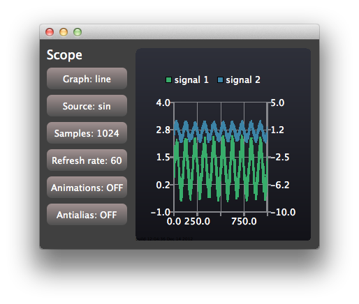
The oscilloscope application demonstrates how to use the Qt Charts QML API to implement an application with strict performance requirements. The application uses generated data with configurable characteristics to mimic a simple oscilloscope user interface.
To get information about actual rendering speed shown in the application output console, you can set QSG_RENDER_TIMING = 1 to your run environment settings. To do so go to Projects - Run - Run environment in Qt Creator and select Add. Then you can experiment with the different configurable options of the example application to find the configuration that gives you the best performance in your environment.
Running the Example
To run the example from Qt Creator, open the Welcome mode and select the example from Examples. For more information, visit Building and Running an Example.
Creating Views
The application window is shared by control and scope views:
Item {
    id: main
    width: 600
    height: 400

    ControlPanel {
        id: controlPanel
        anchors.top: parent.top
        anchors.topMargin: 10
        anchors.bottom: parent.bottom
        anchors.left: parent.left
        anchors.leftMargin: 10
    ...
    ScopeView {
        id: scopeView
        anchors.top: parent.top
        anchors.bottom: parent.bottom
        anchors.right: parent.right
        anchors.left: controlPanel.right
        height: main.height

        onOpenGLSupportedChanged: {
            if (!openGLSupported) {
                controlPanel.openGLButton.enabled = false
                controlPanel.openGLButton.currentSelection = 0
            }
        }
    }
ControlView implements the buttons used for configuring. ScopeView uses a ChartView to show a chart with two line series:
ChartView {
    id: chartView
    animationOptions: ChartView.NoAnimation
    theme: ChartView.ChartThemeDark
    property bool openGL: true
    property bool openGLSupported: true
    onOpenGLChanged: {
        if (openGLSupported) {
            series("signal 1").useOpenGL = openGL;
            series("signal 2").useOpenGL = openGL;
        }
    }
    Component.onCompleted: {
        if (!series("signal 1").useOpenGL) {
            openGLSupported = false
            openGL = false
        }
    }

    ValueAxis {
        id: axisY1
        min: -1
        max: 4
    }

    ValueAxis {
        id: axisY2
        min: -10
        max: 5
    }

    ValueAxis {
        id: axisX
        min: 0
        max: 1024
    }

    LineSeries {
        id: lineSeries1
        name: "signal 1"
        axisX: axisX
        axisY: axisY1
        useOpenGL: chartView.openGL
    }
    LineSeries {
        id: lineSeries2
        name: "signal 2"
        axisX: axisX
        axisYRight: axisY2
        useOpenGL: chartView.openGL
    }
    ...
The data of the line series is updated with a QML timer. In a real life application the updating could be triggered with a signal from Qt C++ code.
Timer {
    id: refreshTimer
    interval: 1 / 60 * 1000 // 60 Hz
    running: true
    repeat: true
    onTriggered: {
        dataSource.update(chartView.series(0));
        dataSource.update(chartView.series(1));
    }
}
The oscilloscope also allows you to switch the type of the series used for visualizing the signal sources. This is implemented by dynamically destroying and creating series:
function changeSeriesType(type) {
    chartView.removeAllSeries();

    // Create two new series of the correct type. Axis x is the same for both of the series,
    // but the series have their own y-axes to make it possible to control the y-offset
    // of the "signal sources".
    if (type == "line") {
        var series1 = chartView.createSeries(ChartView.SeriesTypeLine, "signal 1",
                                             axisX, axisY1);
        series1.useOpenGL = chartView.openGL

        var series2 = chartView.createSeries(ChartView.SeriesTypeLine, "signal 2",
                                             axisX, axisY2);
        series2.useOpenGL = chartView.openGL
    } else {
        var series1 = chartView.createSeries(ChartView.SeriesTypeScatter, "signal 1",
                                             axisX, axisY1);
        series1.markerSize = 2;
        series1.borderColor = "transparent";
        series1.useOpenGL = chartView.openGL

        var series2 = chartView.createSeries(ChartView.SeriesTypeScatter, "signal 2",
                                             axisX, axisY2);
        series2.markerSize = 2;
        series2.borderColor = "transparent";
        series2.useOpenGL = chartView.openGL
    }
}

function createAxis(min, max) {
    // The following creates a ValueAxis object that can be then set as a x or y axis for a series
    return Qt.createQmlObject("import QtQuick 2.0; import QtCharts 2.0; ValueAxis { min: "
                              + min + "; max: " + max + " }", chartView);
}
© 2020 The Qt Company Ltd. Documentation contributions included herein are the copyrights of their respective owners. The documentation provided herein is licensed under the terms of the GNU Free Documentation License version 1.3 as published by the Free Software Foundation. Qt and respective logos are trademarks of The Qt Company Ltd. in Finland and/or other countries worldwide. All other trademarks are property of their respective owners.