
Qt Quick 2 Axis Dragging Example
Implementing axis dragging in QML.
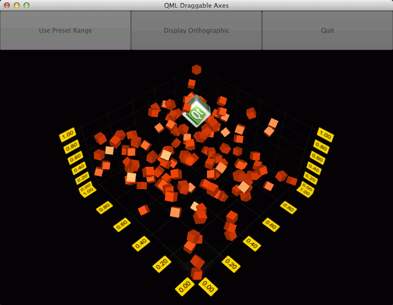
The Qt Quick 2 axis dragging example concentrates on showing how to implement axis range changing by dragging axis labels in QML. It also gives a quick peek to two other new features in Qt Data Visualization 1.1: orthographic projection and dynamic custom item handling.
Running the Example
To run the example from Qt Creator, open the Welcome mode and select the example from Examples. For more information, visit Building and Running an Example.
Overriding Default Input Handling
First we deactivate the default input handling mechanism by setting the active input handler of Scatter3D graph to null:
Scatter3D {
    id: scatterGraph
    inputHandler: null
    ...
Then we add a MouseArea and set it to fill the parent, which is the same Item our scatterGraph is contained in. We also set it to accept only left mouse button presses, as in this example we are not interested in other buttons:
MouseArea {
    anchors.fill: parent
    hoverEnabled: true
    acceptedButtons: Qt.LeftButton
    ...
Then we need to listen to mouse presses, and when caught, send a selection query to the graph:
onPressed: {
    scatterGraph.scene.selectionQueryPosition = Qt.point(mouse.x, mouse.y);
}
Current mouse position, that will be needed for move distance calculation, is caught in onPositionChanged:
onPositionChanged: {
    currentMouseX = mouse.x;
    currentMouseY = mouse.y;
    ...
At the end of onPositionChanged, we'll save the previous mouse position for move distance calculation that will be introduced later:
...
previousMouseX = currentMouseX;
previousMouseY = currentMouseY;
}
Translating Mouse Movement to Axis Range Change
in scatterGraph we will need to listen to onSelectedElementChanged signal. The signal is emitted after the selection query has been made in the onPressed of inputArea. We set the element type into a property we defined (property int selectedAxisLabel: -1) in our main component, since it is of a type we are interested in:
onSelectedElementChanged: {
    if (selectedElement >= AbstractGraph3D.ElementAxisXLabel
            && selectedElement <= AbstractGraph3D.ElementAxisZLabel)
        selectedAxisLabel = selectedElement
    else
        selectedAxisLabel = -1
}
Then, back in the onPositionChanged of inputArea, we check if a mouse button is pressed and if we have a current axis label selection. If the conditions are met, we'll call the function that does the conversion from mouse movement to axis range update:
...
if (pressed && selectedAxisLabel != -1)
    dragAxis();
...
The conversion is easy in this case, as we have a fixed camera rotation. We can use some precalculated values, calculate mouse move distance, and apply the values to the selected axis range:
function dragAxis() {
    // Do nothing if previous mouse position is uninitialized
    if (previousMouseX === -1)
        return

    // Directional drag multipliers based on rotation. Camera is locked to 45 degrees, so we
    // can use one precalculated value instead of calculating xx, xy, zx and zy individually
    var cameraMultiplier = 0.70710678

    // Calculate the mouse move amount
    var moveX = currentMouseX - previousMouseX
    var moveY = currentMouseY - previousMouseY

    // Adjust axes
    switch (selectedAxisLabel) {
    case AbstractGraph3D.ElementAxisXLabel:
        var distance = ((moveX - moveY) * cameraMultiplier) / dragSpeedModifier
        // Check if we need to change min or max first to avoid invalid ranges
        if (distance > 0) {
            scatterGraph.axisX.min -= distance
            scatterGraph.axisX.max -= distance
        } else {
            scatterGraph.axisX.max -= distance
            scatterGraph.axisX.min -= distance
        }
        break
    case AbstractGraph3D.ElementAxisYLabel:
        distance = moveY / dragSpeedModifier
        // Check if we need to change min or max first to avoid invalid ranges
        if (distance > 0) {
            scatterGraph.axisY.max += distance
            scatterGraph.axisY.min += distance
        } else {
            scatterGraph.axisY.min += distance
            scatterGraph.axisY.max += distance
        }
        break
    case AbstractGraph3D.ElementAxisZLabel:
        distance = ((moveX + moveY) * cameraMultiplier) / dragSpeedModifier
        // Check if we need to change min or max first to avoid invalid ranges
        if (distance > 0) {
            scatterGraph.axisZ.max += distance
            scatterGraph.axisZ.min += distance
        } else {
            scatterGraph.axisZ.min += distance
            scatterGraph.axisZ.max += distance
        }
        break
    }
}
For a more sophisticated conversion from mouse movement to axis range update, see this example.
Other Features
The example also demonstrates how to use orthographic projection and how to update properties of a custom item on the fly.
Orthographic projection is very simple. You'll just need to change orthoProjection property of scatterGraph. In this example we have a button for toggling it on and off:
NewButton {
    id: orthoToggle
    width: parent.width / 3
    text: "Display Orthographic"
    anchors.left: rangeToggle.right
    onClicked: {
        if (scatterGraph.orthoProjection) {
            text = "Display Orthographic";
            scatterGraph.orthoProjection = false
            // Orthographic projection disables shadows, so we need to switch them back on
            scatterGraph.shadowQuality = AbstractGraph3D.ShadowQualityLow
        } else {
            text = "Display Perspective";
            scatterGraph.orthoProjection = true
        }
    }
}
For custom items, first we'll add one in the customItemList of scatterGraph:
customItemList: [
    Custom3DItem {
        id: qtCube
        meshFile: ":/mesh/cube"
        textureFile: ":/texture/texture"
        position: Qt.vector3d(0.65,0.35,0.65)
        scaling: Qt.vector3d(0.3,0.3,0.3)
    }
]
We have implemented a timer to add, remove, and rotate all the items in the graph, and we'll use the same timer for rotating the custom item:
onTriggered: {
    rotationAngle = rotationAngle + 1
    qtCube.setRotationAxisAndAngle(Qt.vector3d(1,0,1), rotationAngle)
    ...
Example Contents
© 2020 The Qt Company Ltd. Documentation contributions included herein are the copyrights of their respective owners. The documentation provided herein is licensed under the terms of the GNU Free Documentation License version 1.3 as published by the Free Software Foundation. Qt and respective logos are trademarks of The Qt Company Ltd. in Finland and/or other countries worldwide. All other trademarks are property of their respective owners.