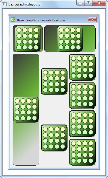
基本图形布局示例
演示如何创建基本图形布局。
基本图形布局示例展示了如何使用QGraphicsView:QGraphicsLinearLayout 和QGraphicsGridLayout 中的布局类。此外,它还展示了如何编写自己的自定义布局项。

窗口类定义
Window 类是QGraphicsWidget 的子类。它有一个构造函数,参数是QGraphicsWidget parent 。
class Window : public QGraphicsWidget
{
    Q_OBJECT
public:
    Window(QGraphicsWidget *parent = nullptr);

};
窗口类的实现
Window 的构造函数实例化了一个垂直方向的QGraphicsLinearLayout 对象windowLayout 。我们实例化另一个QGraphicsLinearLayout 对象,即linear ,它的父对象是windowLayout 。接着,我们创建一个LayoutItem 对象,即item ,并使用addItem() 函数将其添加到linear 。我们还为item 提供了一个stretchFactor 。
    QGraphicsLinearLayout *windowLayout = new QGraphicsLinearLayout(Qt::Vertical);
    QGraphicsLinearLayout *linear = new QGraphicsLinearLayout(windowLayout);
    LayoutItem *item = new LayoutItem;
    linear->addItem(item);
    linear->setStretchFactor(item, 1);
我们重复上述过程:
- 创建一个新的
LayoutItem、 - 添加项目
linear,并 - 提供一个伸展因子。
    item = new LayoutItem;
    linear->addItem(item);
    linear->setStretchFactor(item, 3);
    windowLayout->addItem(linear);
然后,我们在windowLayout 中添加linear ,嵌套两个QGraphicsLinearLayout 对象。除了QGraphicsLinearLayout 外,我们还使用了一个QGraphicsGridLayout 对象grid ,它是一个 4x3 网格,其中一些单元格跨越到其他行。
我们创建了 7 个LayoutItem 对象,并使用addItem() 函数将它们放入grid ,如下代码片段所示:
    QGraphicsGridLayout *grid = new QGraphicsGridLayout(windowLayout);
    item = new LayoutItem;
    grid->addItem(item, 0, 0, 4, 1);
    item = new LayoutItem;
    item->setMaximumHeight(item->minimumHeight());
    grid->addItem(item, 0, 1, 2, 1, Qt::AlignVCenter);
    item = new LayoutItem;
    item->setMaximumHeight(item->minimumHeight());
    grid->addItem(item, 2, 1, 2, 1, Qt::AlignVCenter);
    item = new LayoutItem;
    grid->addItem(item, 0, 2);
    item = new LayoutItem;
    grid->addItem(item, 1, 2);
    item = new LayoutItem;
    grid->addItem(item, 2, 2);
    item = new LayoutItem;
    grid->addItem(item, 3, 2);
    windowLayout->addItem(grid);
我们添加到grid 的第一个项目位于左上角的单元格中,横跨四行。接下来的两个项目放在第二列,跨两行。每个项目的maximumHeight() 和minimumHeight() 设置为相等,这样它们就不会垂直展开。因此,这些项目在其单元格中将无法垂直放置。因此,我们使用Qt::AlignVCenter 指定它们应垂直排列在单元格的中心。
最后,grid 本身被添加到windowLayout 中。与QGridLayout::addItem() 不同,QGraphicsGridLayout::addItem() 需要为其参数提供行和列,指定项目应放置在哪个单元格中。此外,如果省略rowSpan 和columnSpan 参数,它们将默认为 1。
请注意,我们并没有为构建的每个LayoutItem 指定父对象,因为所有这些项目都将添加到windowLayout 中。当我们将项目添加到布局中时,它将自动重新定向到安装布局的 widget 上。
    setLayout(windowLayout);
setWindowTitle(tr("Basic Graphics Layouts Example"));现在,我们已设置好grid 并将其添加到windowLayout ,然后使用QGraphicsWidget::setLayout() 将windowLayout 安装到窗口对象上,并设置窗口标题。
布局项类定义
LayoutItem 类是QGraphicsLayoutItem 和QGraphicsItem 的子类。它有一个构造函数、一个析构函数和一些必要的重实现。由于它继承了QGraphicsLayoutItem ,因此必须重新实现 {QGraphicsLayoutItem::setGeometry()}{setGeometry()} 和 {QGraphicsLayoutItem::sizeHint()}{sizeHint()} 。除此之外,它还继承了QGraphicsItem ,因此必须重新实现 {QGraphicsItem::boundingRect()}{boundingRect()} 和 {QGraphicsItem::paint()}{paint()} 。
class LayoutItem : public QGraphicsLayoutItem, public QGraphicsItem
{
public:
    LayoutItem(QGraphicsItem *parent = nullptr);

    // Inherited from QGraphicsLayoutItem
    void setGeometry(const QRectF &geom) override;
    QSizeF sizeHint(Qt::SizeHint which, const QSizeF &constraint = QSizeF()) const override;

    // Inherited from QGraphicsItem
    QRectF boundingRect() const override;
    void paint(QPainter *painter, const QStyleOptionGraphicsItem *option, QWidget *widget = nullptr) override;

private:
    QPixmap m_pix;
};
LayoutItem 类也有一个QPixmap 的私有实例,即m_pix 。
布局项类的实现
在LayoutItem 的构造函数中,m_pix 被实例化,block.png 图像被载入其中。
LayoutItem::LayoutItem(QGraphicsItem *parent)
    : QGraphicsLayoutItem(), QGraphicsItem(parent),
      m_pix(QPixmap(QLatin1String(":/images/block.png")))
{
    setGraphicsItem(this);
}
我们使用Q_UNUSED() 宏来防止编译器生成有关未使用参数的警告。
void LayoutItem::paint(QPainter *painter, const QStyleOptionGraphicsItem *option,
                       QWidget *widget)
{
    Q_UNUSED(widget);
    Q_UNUSED(option);

    QRectF frame(QPointF(0, 0), geometry().size());
    const QSize pmSize = m_pix.size();
    QGradientStops stops;
paint() 函数的原理是绘制背景矩形,然后在像素图周围绘制一个矩形。
    // paint a background rect (with gradient)
    QLinearGradient gradient(frame.topLeft(), frame.topLeft() + QPointF(200,200));
    stops << QGradientStop(0.0, QColor(60, 60,  60));
    stops << QGradientStop(frame.height() / 2 / frame.height(), QColor(102, 176, 54));

    //stops << QGradientStop(((frame.height() + h)/2 )/frame.height(), QColor(157, 195,  55));
    stops << QGradientStop(1.0, QColor(215, 215, 215));
    gradient.setStops(stops);
    painter->setBrush(QBrush(gradient));
    painter->drawRoundedRect(frame, 10.0, 10.0);

    // paint a rect around the pixmap (with gradient)
    QPointF pixpos = frame.center() - (QPointF(pmSize.width(), pmSize.height()) / 2);
    QRectF innerFrame(pixpos, pmSize);
    innerFrame.adjust(-4, -4, 4, 4);
    gradient.setStart(innerFrame.topLeft());
    gradient.setFinalStop(innerFrame.bottomRight());
    stops.clear();
    stops << QGradientStop(0.0, QColor(215, 255, 200));
    stops << QGradientStop(0.5, QColor(102, 176, 54));
    stops << QGradientStop(1.0, QColor(0, 0,  0));
    gradient.setStops(stops);
    painter->setBrush(QBrush(gradient));
    painter->drawRoundedRect(innerFrame, 10.0, 10.0);
    painter->drawPixmap(pixpos, m_pix);
}
boundingRect() 的重新实现将把左上角设置为 (0,0),其大小与布局项geometry() 的大小相同。这就是我们要绘制的区域。
setGeometry() 的重新实现只需调用其基类实现。不过,由于这将改变边界矩形,我们还必须调用prepareGeometryChange()。最后,我们根据geom.topLeft() 移动项目。
void LayoutItem::setGeometry(const QRectF &geom)
{
    prepareGeometryChange();
    QGraphicsLayoutItem::setGeometry(geom);
    setPos(geom.topLeft());
}
由于我们不希望项目的尺寸小于像素图,因此必须确保返回的尺寸提示大于m_pix 。我们还在周围添加了一些额外的空间,以便稍后绘制边框。或者,也可以缩放像素图,防止项目变得比像素图小。首选尺寸与最小尺寸提示相同,而我们将最大尺寸设置为一个较大的值
QSizeF LayoutItem::sizeHint(Qt::SizeHint which, const QSizeF &constraint) const
{
    switch (which) {
    case Qt::MinimumSize:
    case Qt::PreferredSize:
        // Do not allow a size smaller than the pixmap with two frames around it.
        return m_pix.size() + QSize(12, 12);
    case Qt::MaximumSize:
        return QSizeF(1000,1000);
    default:
        break;
    }
    return constraint;
}
© 2025 The Qt Company Ltd. Documentation contributions included herein are the copyrights of their respective owners. The documentation provided herein is licensed under the terms of the GNU Free Documentation License version 1.3 as published by the Free Software Foundation. Qt and respective logos are trademarks of The Qt Company Ltd. in Finland and/or other countries worldwide. All other trademarks are property of their respective owners.

