
绘图路径示例
“绘图路径”示例演示了如何使用绘图路径构建用于渲染的复杂图形。
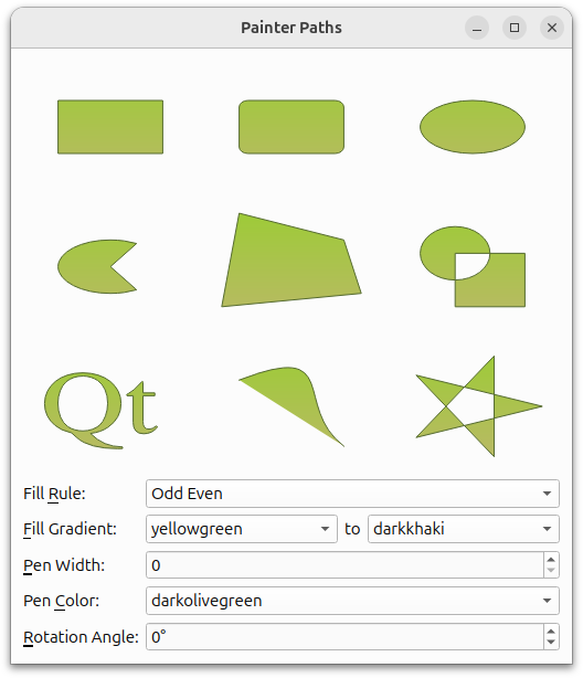
QPainterPath 类提供了一个用于绘制操作的容器,支持构建和复用图形形状。
绘图路径是由多个图形构建块(如矩形、椭圆、直线和曲线)组成的对象,可用于填充、勾勒轮廓和裁剪。 与普通绘图操作相比,绘图路径的主要优势在于:复杂形状只需创建一次,但只需调用QPainter::drawPath() 即可多次绘制。
该示例包含两个类:
RenderArea类,这是一个自定义小部件,用于显示单个绘图路径。Window类,它是应用程序的主窗口,用于显示多个RenderArea控件,并允许用户操作画笔路径的填充、笔型、颜色和旋转角度。
首先我们将回顾Window 类,然后将了解RenderArea 类。
窗口类定义
Window 类继承自QWidget 类,它是应用程序的主窗口,显示了多个RenderArea 控件,并允许用户操作绘图路径的填充、画笔、颜色和旋转角度。
class Window : public QWidget
{
    Q_OBJECT

public:
    Window();

private slots:
    void fillRuleChanged();
    void fillGradientChanged();
void penColorChanged();我们声明了三个私有槽来响应用户关于填充和颜色的输入:fillRuleChanged() 、fillGradientChanged() 和penColorChanged() 。
当用户更改笔宽和旋转角度时,新值会通过QSpinBox::valueChanged() 信号直接传递给RenderArea 控件。 我们必须实现槽来更新填充和颜色,是因为QComboBox 没有提供类似的、将新值作为参数传递的信号;因此,在更新RenderArea 控件之前,我们需要先获取新值(或多个新值)。
private:
    void populateWithColors(QComboBox *comboBox);
QVariant currentItemData(QComboBox *comboBox);我们还声明了几个私有的辅助函数:populateWithColors() 会将 Qt XML 所识别的颜色名称对应的项填入给定的QComboBox 中,而currentItemData() 则返回给定QComboBox 的当前项。
    QList<RenderArea*> renderAreas;
    QLabel *fillRuleLabel;
    QLabel *fillGradientLabel;
    QLabel *fillToLabel;
    QLabel *penWidthLabel;
    QLabel *penColorLabel;
    QLabel *rotationAngleLabel;
    QComboBox *fillRuleComboBox;
    QComboBox *fillColor1ComboBox;
    QComboBox *fillColor2ComboBox;
    QSpinBox *penWidthSpinBox;
    QComboBox *penColorComboBox;
    QSpinBox *rotationAngleSpinBox;
};接着,我们声明主窗口小部件的各个组件。此外,我们还声明了一个便利常量,用于指定RenderArea 小部件的数量。
窗口类的实现
在Window 的构造函数中,我们定义了各种绘制路径,并创建了相应的RenderArea 控件来渲染图形:
Window::Window()
{
    QPainterPath rectPath;
    rectPath.moveTo(20.0, 30.0);
    rectPath.lineTo(80.0, 30.0);
    rectPath.lineTo(80.0, 70.0);
    rectPath.lineTo(20.0, 70.0);
rectPath.closeSubpath();我们使用QPainterPath::moveTo()和QPainterPath::lineTo()函数构建一个具有锐角的矩形。
QPainterPath::moveTo() 将当前点移动到作为参数传递的点。绘制路径是由多个图形构建块(即子路径)组成的对象。移动当前点也会启动一个新的子路径(当新路径启动时,会隐式关闭之前的当前路径)。QPainterPath::lineTo() 函数会从当前点到给定的终点添加一条直线。画线完成后,当前点将更新为该直线的终点。
我们首先移动当前点以开始一个新的子路径,并绘制矩形的三个边。然后调用QPainterPath::closeSubpath()函数,该函数会绘制一条延伸至当前子路径起点的直线。当当前子路径闭合时,系统会自动开始一个新的子路径。新路径的当前点为(0, 0)。 我们也可以调用 `QPainterPath::lineTo()` 来绘制最后一条线段,然后使用 `QPainterPath::moveTo()` 函数显式地开始一个新的子路径。
QPainterPath 此外还提供了QPainterPath::addRect() 便捷函数,它将给定的矩形作为闭合子路径添加到路径中。该矩形将以顺时针方向的一组线条形式添加。添加完 rect 后,绘图路径的当前位置位于矩形的左上角。
    QPainterPath roundRectPath;
    roundRectPath.moveTo(80.0, 35.0);
    roundRectPath.arcTo(70.0, 30.0, 10.0, 10.0, 0.0, 90.0);
    roundRectPath.lineTo(25.0, 30.0);
    roundRectPath.arcTo(20.0, 30.0, 10.0, 10.0, 90.0, 90.0);
    roundRectPath.lineTo(20.0, 65.0);
    roundRectPath.arcTo(20.0, 60.0, 10.0, 10.0, 180.0, 90.0);
    roundRectPath.lineTo(75.0, 70.0);
    roundRectPath.arcTo(70.0, 60.0, 10.0, 10.0, 270.0, 90.0);
roundRectPath.closeSubpath();接着,我们构造一个圆角矩形。与之前一样,我们使用QPainterPath::moveTo() 和QPainterPath::lineTo() 函数绘制矩形的边。为了创建圆角,我们使用QPainterPath::arcTo() 函数。
QPainterPath::arcTo() 函数会绘制一个占据给定矩形(由QRect 或矩形坐标指定)的弧,从给定的起始角度开始,并沿逆时针方向延伸给定的度数。角度以度为单位指定。 若需绘制顺时针弧线,可使用负角度进行指定。如果当前点与弧线的起始点尚未连接,该函数会将两者连接起来。
    QPainterPath ellipsePath;
    ellipsePath.moveTo(80.0, 50.0);
ellipsePath.arcTo(20.0, 30.0, 60.0, 40.0, 0.0, 360.0);我们还使用QPainterPath::arcTo() 函数来构造椭圆路径。首先,我们将当前点移动到新路径的起始位置。然后,我们调用QPainterPath::arcTo() 函数,将起始角度设为 0.0,并将 360.0 度作为最后一个参数,从而绘制出一个椭圆。
同样,QPainterPath 提供了一个便捷函数(QPainterPath::addEllipse()),它能在给定的边界矩形内绘制椭圆并将其添加到绘图路径中。如果当前子路径是闭合的,则会开始一个新的子路径。该椭圆由顺时针曲线组成,起始和终点均为零度(即 3 点钟位置)。
    QPainterPath piePath;
    piePath.moveTo(50.0, 50.0);
    piePath.arcTo(20.0, 30.0, 60.0, 40.0, 60.0, 240.0);
    piePath.closeSubpath();
在构建饼图路径时,我们继续组合使用上述函数:首先移动当前点,从而开始一个新的子路径。然后,我们绘制一条从图表中心到弧线的直线,并绘制弧线本身。当关闭子路径时,系统会隐式地绘制最后一条返回图表中心的直线。
    QPainterPath polygonPath;
    polygonPath.moveTo(10.0, 80.0);
    polygonPath.lineTo(20.0, 10.0);
    polygonPath.lineTo(80.0, 30.0);
    polygonPath.lineTo(90.0, 70.0);
    polygonPath.closeSubpath();
绘制多边形等同于绘制矩形。
QPainterPath 还提供了QPainterPath::addPolygon() 便捷函数,该函数将给定的多边形作为新的子路径添加到路径中。添加多边形后的当前位置即为多边形的最后一点。
    QPainterPath groupPath;
    groupPath.moveTo(60.0, 40.0);
    groupPath.arcTo(20.0, 20.0, 40.0, 40.0, 0.0, 360.0);
    groupPath.moveTo(40.0, 40.0);
    groupPath.lineTo(40.0, 80.0);
    groupPath.lineTo(80.0, 80.0);
    groupPath.lineTo(80.0, 40.0);
groupPath.closeSubpath();QPainterPath::lineTo然后,我们创建一条由一组子路径组成的路径:首先移动当前点,并使用QPainterPath::arcTo()函数创建一个圆,起始角度为0.0,最后一个参数为360度,这与我们创建椭圆路径时的方法相同。 接着再次移动当前点,开始一个新的子路径,并使用 ` ()` 函数绘制正方形的三个边。
现在,当我们调用QPainterPath::closeSubpath()函数时,最后一侧便会生成。请记住,QPainterPath::closeSubpath()函数会绘制一条线段连接到当前子路径的起始点,即正方形。
QPainterPath 提供一个便捷函数QPainterPath::addPath(),用于将给定的路径添加到调用该函数的路径中。
    QPainterPath textPath;
    QFont timesFont("Times", 50);
    timesFont.setStyleStrategy(QFont::ForceOutline);
textPath.addText(10, 70, timesFont, tr("Qt"));在创建文本路径时,我们首先创建字体。然后设置字体的样式策略,该策略会告知字体匹配算法应使用何种类型的字体来查找合适的默认字体族。QFont::ForceOutline 会强制使用轮廓字体。
要构建文本,我们使用 `QPainterPath::addText()` 函数,该函数会将给定的文本作为由指定字体生成的闭合子路径集添加到路径中。这些子路径的位置经过调整,使得文本基线的左端位于指定点上。
    QPainterPath bezierPath;
    bezierPath.moveTo(20, 30);
    bezierPath.cubicTo(80, 0, 50, 50, 80, 80);
要创建贝塞尔路径,我们使用 `QPainterPath::cubicTo()` 函数,该函数会在当前点与给定的终点之间,利用给定的控制点添加一条贝塞尔曲线。曲线添加完成后,当前点将更新为曲线的终点。
在此情况下,我们省略了闭合子路径的步骤,因此仅得到一条简单的曲线。但曲线端点至子路径起点的逻辑连线仍然存在;如应用程序主窗口所示,当填充路径时,该连线会变得可见。
    QPainterPath starPath;
    starPath.moveTo(90, 50);
    for (int i = 1; i < 5; ++i) {
        starPath.lineTo(50 + 40 * std::cos(0.8 * i * M_PI),
                        50 + 40 * std::sin(0.8 * i * M_PI));
    }
starPath.closeSubpath();我们构建的最终路径表明,仅使用前文提到的QPainterPath::moveTo()、QPainterPath::lineTo() 和QPainterPath::closeSubpath() 函数,即可通过 `QPainterPath ` 绘制相当复杂的形状。
    renderAreas.push_back(new RenderArea(rectPath));
    renderAreas.push_back(new RenderArea(roundRectPath));
    renderAreas.push_back(new RenderArea(ellipsePath));
    renderAreas.push_back(new RenderArea(piePath));
    renderAreas.push_back(new RenderArea(polygonPath));
    renderAreas.push_back(new RenderArea(groupPath));
    renderAreas.push_back(new RenderArea(textPath));
    renderAreas.push_back(new RenderArea(bezierPath));
renderAreas.push_back(new RenderArea(starPath));现在我们已经创建了所有需要的绘图路径,接下来为每个路径创建一个对应的RenderArea 控件。最后,我们通过Q_ASSERT()宏确保渲染区域的数量正确。
    fillRuleComboBox = new QComboBox;
    fillRuleComboBox->addItem(tr("Odd Even"), Qt::OddEvenFill);
    fillRuleComboBox->addItem(tr("Winding"), Qt::WindingFill);

    fillRuleLabel = new QLabel(tr("Fill &Rule:"));
    fillRuleLabel->setBuddy(fillRuleComboBox);
然后,我们创建与绘制路径填充规则关联的小部件。
Qt XML 中提供了两种填充规则:Qt::OddEvenFill 规则通过从点到形状外部某处绘制一条水平线,并统计交点数量来判断该点是否位于形状内部。如果交点数量为奇数,则该点位于形状内部。此规则为默认规则。
Qt::WindingFill 规则通过从点到形状外部某处画一条水平线,来判断该点是否位于形状内部。然后,它判断每处交点处该线的方向是向上还是向下。通过将各交点的方向求和来确定环绕数。如果该数值不为零,则该点位于形状内部。
在大多数情况下,Qt::WindingFill 规则可视为闭合图形的相交规则。
    fillColor1ComboBox = new QComboBox;
    populateWithColors(fillColor1ComboBox);
    fillColor1ComboBox->setCurrentIndex(fillColor1ComboBox->findText("mediumslateblue"));

    fillColor2ComboBox = new QComboBox;
    populateWithColors(fillColor2ComboBox);
    fillColor2ComboBox->setCurrentIndex(fillColor2ComboBox->findText("cornsilk"));

    fillGradientLabel = new QLabel(tr("&Fill Gradient:"));
    fillGradientLabel->setBuddy(fillColor1ComboBox);

    fillToLabel = new QLabel(tr("to"));
    fillToLabel->setSizePolicy(QSizePolicy::Fixed, QSizePolicy::Fixed);

    penWidthSpinBox = new QSpinBox;
    penWidthSpinBox->setRange(0, 20);

    penWidthLabel = new QLabel(tr("&Pen Width:"));
    penWidthLabel->setBuddy(penWidthSpinBox);

    penColorComboBox = new QComboBox;
    populateWithColors(penColorComboBox);
    penColorComboBox->setCurrentIndex(penColorComboBox->findText("darkslateblue"));

    penColorLabel = new QLabel(tr("Pen &Color:"));
    penColorLabel->setBuddy(penColorComboBox);

    rotationAngleSpinBox = new QSpinBox;
    rotationAngleSpinBox->setRange(0, 359);
    rotationAngleSpinBox->setWrapping(true);
    rotationAngleSpinBox->setSuffix(QLatin1String("\xB0"));

    rotationAngleLabel = new QLabel(tr("&Rotation Angle:"));
    rotationAngleLabel->setBuddy(rotationAngleSpinBox);
我们还创建了与填充、画笔和旋转角度相关的其他控件。
    connect(fillRuleComboBox, &QComboBox::activated,
            this, &Window::fillRuleChanged);
    connect(fillColor1ComboBox, &QComboBox::activated,
            this, &Window::fillGradientChanged);
    connect(fillColor2ComboBox, &QComboBox::activated,
            this, &Window::fillGradientChanged);
    connect(penColorComboBox, &QComboBox::activated,
            this, &Window::penColorChanged);

    for (RenderArea *area : std::as_const(renderAreas)) {
        connect(penWidthSpinBox, &QSpinBox::valueChanged,
                area, &RenderArea::setPenWidth);
        connect(rotationAngleSpinBox, &QSpinBox::valueChanged,
                area, &RenderArea::setRotationAngle);
}我们将下拉列表框的activated()信号连接到Window 类中的相关槽,同时将旋转输入框的valueChanged()信号直接连接到RenderArea 控件的相应槽。
    QGridLayout *topLayout = new QGridLayout;

    int i = 0;
    for (RenderArea *area : std::as_const(renderAreas)) {
        topLayout->addWidget(area, i / 3, i % 3);
        ++i;
    }

    QGridLayout *mainLayout = new QGridLayout;
    mainLayout->addLayout(topLayout, 0, 0, 1, 4);
    mainLayout->addWidget(fillRuleLabel, 1, 0);
    mainLayout->addWidget(fillRuleComboBox, 1, 1, 1, 3);
    mainLayout->addWidget(fillGradientLabel, 2, 0);
    mainLayout->addWidget(fillColor1ComboBox, 2, 1);
    mainLayout->addWidget(fillToLabel, 2, 2);
    mainLayout->addWidget(fillColor2ComboBox, 2, 3);
    mainLayout->addWidget(penWidthLabel, 3, 0);
    mainLayout->addWidget(penWidthSpinBox, 3, 1, 1, 3);
    mainLayout->addWidget(penColorLabel, 4, 0);
    mainLayout->addWidget(penColorComboBox, 4, 1, 1, 3);
    mainLayout->addWidget(rotationAngleLabel, 5, 0);
    mainLayout->addWidget(rotationAngleSpinBox, 5, 1, 1, 3);
setLayout(mainLayout);我们将RenderArea 控件添加到一个单独的布局中,然后将该布局与其他控件一起添加到主布局中。
    fillRuleChanged();
    fillGradientChanged();
    penColorChanged();
    penWidthSpinBox->setValue(2);

    setWindowTitle(tr("Painter Paths"));
}最后,我们通过调用fillRuleChanged() 、fillGradientChanged() 和penColorChanged() 槽来初始化RenderArea 小部件,并设置初始笔宽和窗口标题。
void Window::fillRuleChanged()
{
    Qt::FillRule rule = (Qt::FillRule)currentItemData(fillRuleComboBox).toInt();

    for (RenderArea *area : std::as_const(renderAreas))
        area->setFillRule(rule);
}

void Window::fillGradientChanged()
{
    QColor color1 = qvariant_cast<QColor>(currentItemData(fillColor1ComboBox));
    QColor color2 = qvariant_cast<QColor>(currentItemData(fillColor2ComboBox));

    for (RenderArea *area : std::as_const(renderAreas))
        area->setFillGradient(color1, color2);
}

void Window::penColorChanged()
{
    QColor color = qvariant_cast<QColor>(currentItemData(penColorComboBox));

    for (RenderArea *area : std::as_const(renderAreas))
        area->setPenColor(color);
}
私有插槽的实现用于从关联的下拉列表中获取新值(或多个值),并更新 RenderArea 控件。
首先,我们使用私有函数currentItemData() 和模板函数qvariant_cast() 来确定新值(或多个值)。然后,我们为每个RenderArea 小部件调用相应的槽,以更新绘图路径。
void Window::populateWithColors(QComboBox *comboBox)
{
    const QStringList colorNames = QColor::colorNames();
    for (const QString &name : colorNames)
        comboBox->addItem(name, QColor(name));
}
populateWithColors() 函数会通过静态函数QColor::colorNames()提供的、Qt所识别的颜色名称,将相应的项目填充到给定的下拉列表中。
QVariant Window::currentItemData(QComboBox *comboBox)
{
    return comboBox->itemData(comboBox->currentIndex());
}
currentItemData() 函数仅返回给定下拉列表的当前选中项。
RenderArea 类定义
RenderArea 类继承自QWidget ,是一个用于显示单个绘制路径的自定义控件。
class RenderArea : public QWidget
{
    Q_OBJECT

public:
    explicit RenderArea(const QPainterPath &path, QWidget *parent = nullptr);

    QSize minimumSizeHint() const override;
    QSize sizeHint() const override;

public slots:
    void setFillRule(Qt::FillRule rule);
    void setFillGradient(const QColor &color1, const QColor &color2);
    void setPenWidth(int width);
    void setPenColor(const QColor &color);
    void setRotationAngle(int degrees);

protected:
void paintEvent(QPaintEvent *event) override;我们声明了几个公共槽,用于更新RenderArea 控件关联的绘图路径。此外,我们重写了QWidget::minimumSizeHint()和QWidget::sizeHint()函数,以便在应用程序中为RenderArea 控件设定合理尺寸,并重写了QWidget::paintEvent()事件处理程序以绘制其绘图路径。
private:
    QPainterPath path;
    QColor fillColor1;
    QColor fillColor2;
    int penWidth;
    QColor penColor;
    int rotationAngle;
};
RenderArea 类的每个实例都拥有一个QPainterPath 、几种填充颜色、一支画笔的宽度、一支画笔的颜色以及一个旋转角度。
RenderArea 类的实现
构造函数将QPainterPath 作为参数(此外还可选地接受QWidget 父类):
RenderArea::RenderArea(const QPainterPath &path, QWidget *parent)
    : QWidget(parent), path(path)
{
    penWidth = 1;
    rotationAngle = 0;
    setBackgroundRole(QPalette::Base);
}在构造函数中,我们使用QPainterPath 参数初始化RenderArea 控件,同时初始化笔宽和旋转角度。我们还设置了控件的background role ;QPalette::Base 通常为白色。
QSize RenderArea::minimumSizeHint() const
{
    return QSize(50, 50);
}

QSize RenderArea::sizeHint() const
{
    return QSize(100, 100);
}随后,我们重写了QWidget::minimumSizeHint()和QWidget::sizeHint()函数,以便在应用程序中为RenderArea 控件设置一个合理的大小。
void RenderArea::setFillRule(Qt::FillRule rule)
{
    path.setFillRule(rule);
    update();
}

void RenderArea::setFillGradient(const QColor &color1, const QColor &color2)
{
    fillColor1 = color1;
    fillColor2 = color2;
    update();
}

void RenderArea::setPenWidth(int width)
{
    penWidth = width;
    update();
}

void RenderArea::setPenColor(const QColor &color)
{
    penColor = color;
    update();
}

void RenderArea::setRotationAngle(int degrees)
{
    rotationAngle = degrees;
    update();
}各种公共槽通过设置相关属性来更新RenderArea 控件的绘制路径,并调用QWidget::update() 函数,强制控件按照新的渲染首选项进行重绘。
QWidget::update() 槽不会立即触发重绘;而是会调度一个绘制事件,待 Qt 返回主事件循环时进行处理。
void RenderArea::paintEvent(QPaintEvent *)
{
    QPainter painter(this);
    painter.setRenderHint(QPainter::Antialiasing);
绘制事件是要求重绘小部件全部或部分内容的请求。paintEvent() 函数是一个事件处理程序,可以重写它以接收小部件的绘制事件。我们重写该事件处理程序,以渲染RenderArea 小部件的绘制路径。
首先,我们为RenderArea 实例创建一个QPainter ,并设置绘制器的渲染提示。QPainter::RenderHints 用于向QPainter 指定标志,这些标志可能被特定引擎采纳,也可能不被采纳。QPainter::Antialiasing 表示引擎应在可能的情况下对基元边缘进行抗锯齿处理,即在原始像素周围添加额外像素以平滑边缘。
    painter.scale(width() / 100.0, height() / 100.0);
    painter.translate(50.0, 50.0);
    painter.rotate(-rotationAngle);
painter.translate(-50.0, -50.0);然后,我们将QPainter 的坐标系进行缩放,以确保绘制路径以正确尺寸渲染,即当应用程序调整大小时,该路径会随RenderArea 控件一同缩放。 在构建各种绘制路径时,它们均渲染在一个宽度为 100 像素的正方形内,这相当于RenderArea::sizeHint() 。QPainter::scale() 函数通过将RenderArea 控件的当前宽度和高度除以 100 来缩放坐标系。
现在,当我们确认绘图路径尺寸正确后,可以平移坐标系,使绘图路径围绕RenderArea 控件的中心旋转。完成旋转操作后,必须记得将坐标系平移回原位。
    painter.setPen(QPen(penColor, penWidth, Qt::SolidLine, Qt::RoundCap, Qt::RoundJoin));
    QLinearGradient gradient(0, 0, 0, 100);
    gradient.setColorAt(0.0, fillColor1);
    gradient.setColorAt(1.0, fillColor2);
    painter.setBrush(gradient);
    painter.drawPath(path);
}
接着,我们根据实例的渲染首选项设置 `QPainter` 的画笔。创建一个 `QLinearGradient `,并将其颜色设置为与 `RenderArea ` 控件的填充色相对应。最后,设置 `QPainter` 的画笔(渐变会自动转换为 `QBrush`),并使用 `QPainter::drawPath()` 函数绘制 `RenderArea ` 控件的绘制路径。
© 2026 The Qt Company Ltd. Documentation contributions included herein are the copyrights of their respective owners. The documentation provided herein is licensed under the terms of the GNU Free Documentation License version 1.3 as published by the Free Software Foundation. Qt and respective logos are trademarks of The Qt Company Ltd. in Finland and/or other countries worldwide. All other trademarks are property of their respective owners.
