Qt 3D Render Framegraph
A framegraph is the data structure that controls how a scene is rendered.
The Qt 3D Render aspect allows for the rendering algorithm to be entirely data-driven. The controlling data structure is known as the framegraph. Similar to how the Qt 3D ECS (entity component system) allows you to define a so-called Scenegraph by building a scene from a tree of Entities and Components, the framegraph is also a tree structure but one used for a different purpose. Namely, controlling how the scene is rendered.
Over the course of rendering a single frame, a 3D renderer will likely change state many times. The number and nature of these state changes depends upon not only which materials (shaders, mesh geometry, textures and uniform variables) are found within the scene, but also upon which high level rendering scheme you are using.
For example, using a traditional simple forward rendering scheme is very different to using a deferred rendering approach. Other features such as reflections, shadows, multiple viewports, and early z-fill passes all change which states a renderer needs to set over the course of a frame and when those state changes need to occur.
As a comparison, the Qt Quick 2 scenegraph renderer responsible for drawing Qt Quick 2 scenes is hard-wired in C++ to do things like batching of primitives and rendering opaque items followed by rendering of transparent items. In the case of Qt Quick 2 that is perfectly fine as that covers all of the requirements. As you can see from some of the examples listed above, such a hard-wired renderer is not likely to be flexible enough for generic 3D scenes given the multitude of rendering methods available. Or if a renderer could be made flexible enough to cover all such cases, its performance would likely suffer from being too general. To make matters worse, more rendering methods are being researched all of the time. We therefore needed an approach that is both flexible and extensible whilst being simple to use and maintain. Enter the framegraph!
Each node in the framegraph defines a part of the configuration the renderer will use to render the scene. The position of a node in the framegraph tree determines when and where the subtree rooted at that node will be the active configuration in the rendering pipeline. As we will see later, the renderer traverses this tree in order to build up the state needed for your rendering algorithm at each point in the frame.
Obviously if you just want to render a simple cube onscreen you may think this is overkill. However, as soon as you want to start doing slightly more complex scenes this comes in handy. For the common cases, Qt 3D provides some example framegraphs that are ready to use out of the box.
We will demonstrate the flexibility of the framegraph concept by presenting a few examples and the resulting framegraphs.
Please note that unlike the Scenegraph which is composed of Entities and Components, the framegraph is only composed of nested nodes which are all subclasses of QFrameGraphNode . This is because the framegraph nodes are not simulated objects in our virtual world, but rather supporting information.
We will soon see how to construct our first simple framegraph but before that we will introduce the framegraph nodes available to you. Also as with the Scenegraph tree, the QML and C++ APIs are a 1 to 1 match so you can favor the one you like best. For the sake of readability and conciseness, the QML API was chosen for this article.
The beauty of the framegraph is that combining these simple node types, it is possible to configure the renderer to suit your specific needs without touching any hairy, low-level C/C++ rendering code at all.
FrameGraph Rules
In order to construct a correctly functioning framegraph tree, you should know a few rules about how it is traversed and how to feed it to the Qt 3D renderer.
Setting the Framegraph
The FrameGraph tree should be assigned to the activeFrameGraph property of a QRenderSettings component, itself being a component of the root entity in the Qt 3D scene. This is what makes it the active framegraph for the renderer. Of course, since this is a QML property binding, the active framegraph (or parts of it) can be changed on the fly at runtime. For example, if you want to use different rendering approaches for indoor and outdoor scenes or to enable or disable some special effect.
Entity {
    id: sceneRoot
    components: RenderSettings {
         activeFrameGraph: ... // FrameGraph tree
    }
}
Note
activeFrameGraph is the default property of the FrameGraph component in QML.
Entity {
    id: sceneRoot
    components: RenderSettings {
         ... // FrameGraph tree
    }
}
How the Framegraph Is Used
The Qt 3D renderer performs a depth first traversal of the framegraph tree. Note that, because the traversal is depth first, the order in which you define nodes is important.
When the renderer reaches a leaf node of the framegraph, it collects together all of the state specified by the path from the leaf node to the root node. This defines the state used to render a section of the frame. If you are interested in the internals of Qt 3D, this collection of state is called a RenderView.
Given the configuration contained in a RenderView, the renderer collects together all of the Entities in the Scenegraph to be rendered, and from them builds a set of RenderCommands and associates them with the RenderView.
The combination of RenderView and set of RenderCommands is passed over for submission to OpenGL.
When this is repeated for each leaf node in the framegraph, the frame is complete and the renderer calls QOpenGLContext::swapBuffers() to display the frame.
At its heart, the framegraph is a data-driven method for configuring the Qt 3D renderer. Due to its data-driven nature, we can change configuration at runtime, allow non-C++ developers or designers to change the structure of a frame, and try out new rendering approaches without having to write thousands of lines of boiler plate code.
Framegraph Examples
Now that you know the rules to abide by when writing a framegraph tree, we will go over a few examples and break them down.
A Simple Forward Renderer
Forward rendering is when you use OpenGL in its traditional manner and render directly to the backbuffer one object at a time shading each one as we go. This is opposed to deferred rendering where we render to an intermediate G-buffer. Here is a simple FrameGraph that can be used for forward rendering:
Viewport {
     normalizedRect: Qt.rect(0.0, 0.0, 1.0, 1.0)
     property alias camera: cameraSelector.camera

     ClearBuffers {
          buffers: ClearBuffers.ColorDepthBuffer

          CameraSelector {
               id: cameraSelector
          }
     }
}
As you can see, this tree has a single leaf and is composed of 3 nodes in total as shown in the following diagram.
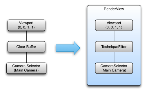
Using the rules defined above , this framegraph tree yields a single RenderView with the following configuration:
Leaf Node -> RenderView
Viewport that fills the entire screen (uses normalized coordinates to make it easy to support nested viewports)
Color and Depth buffers are set to be cleared
Camera specified in the exposed camera property
Several different FrameGraph trees can produce the same rendering result. As long as the state collected from leaf to root is the same, the result will also be the same. It is best to put state that remains constant longest nearer to the root of the framegraph as this will result in fewer leaf nodes, and hence, fewer RenderViews overall.
Viewport {
     normalizedRect: Qt.rect(0.0, 0.0, 1.0, 1.0)
     property alias camera: cameraSelector.camera

     CameraSelector {
          id: cameraSelector

          ClearBuffers {
               buffers: ClearBuffers.ColorDepthBuffer
          }
     }
}
CameraSelector { Viewport { normalizedRect: Qt.rect(0.0, 0.0, 1.0, 1.0) ClearBuffers { buffers: ClearBuffers.ColorDepthBuffer } } }
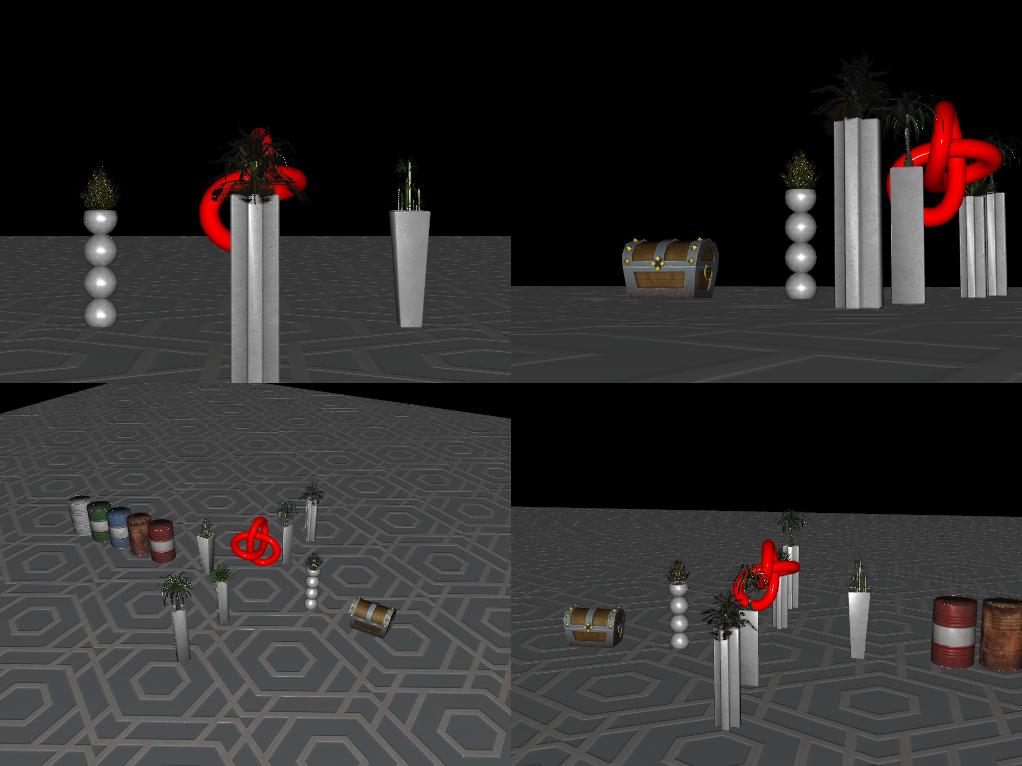
A Multi Viewport FrameGraph
Let us move on to a slightly more complex example that renders a Scenegraph from the point of view of 4 virtual cameras into the 4 quadrants of the window. This is a common configuration for 3D CAD or modelling tools or could be adjusted to help with rendering a rear-view mirror in a car racing game or a CCTV camera display.
 Viewport { id: mainViewport normalizedRect: Qt.rect(0, 0, 1, 1) property alias Camera: cameraSelectorTopLeftViewport.camera property alias Camera: cameraSelectorTopRightViewport.camera property alias Camera: cameraSelectorBottomLeftViewport.camera property alias Camera: cameraSelectorBottomRightViewport.camera ClearBuffers { buffers: ClearBuffers.ColorDepthBuffer } Viewport { id: topLeftViewport normalizedRect: Qt.rect(0, 0, 0.5, 0.5) CameraSelector { id: cameraSelectorTopLeftViewport } } Viewport { id: topRightViewport normalizedRect: Qt.rect(0.5, 0, 0.5, 0.5) CameraSelector { id: cameraSelectorTopRightViewport } } Viewport { id: bottomLeftViewport normalizedRect: Qt.rect(0, 0.5, 0.5, 0.5) CameraSelector { id: cameraSelectorBottomLeftViewport } } Viewport { id: bottomRightViewport normalizedRect: Qt.rect(0.5, 0.5, 0.5, 0.5) CameraSelector { id: cameraSelectorBottomRightViewport } } }
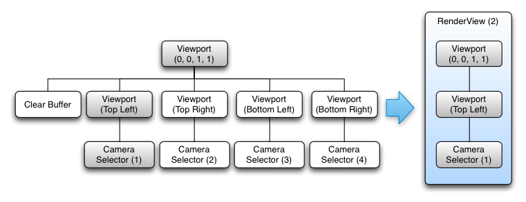
This tree is a bit more complex with 5 leaves. Following the same rules as before we construct 5 RenderView objects from the FrameGraph. The following diagrams show the construction for the first two RenderViews. The remaining RenderViews are very similar to the second diagram just with the other sub-trees.
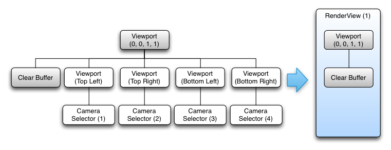
In full, the RenderViews created are:
RenderView (1)
Fullscreen viewport defined
Color and Depth buffers are set to be cleared
RenderView (2)
Fullscreen viewport defined
Sub viewport defined (rendering viewport will be scaled relative to its parent)
CameraSelector specified
RenderView (3)
Fullscreen viewport defined
Sub viewport defined (rendering viewport will be scaled relative to its parent)
CameraSelector specified
RenderView (4)
Fullscreen viewport defined
Sub viewport defined (rendering viewport will be scaled relative to its parent)
CameraSelector specified
RenderView (5)
Fullscreen viewport defined
Sub viewport defined (rendering viewport will be scaled relative to its parent)
CameraSelector specified
However, in this case the order is important. If the ClearBuffers node were to be the last instead of the first, this would result in a black screen for the simple reason that everything would be cleared right after having been so carefully rendered. For a similar reason, it could not be used as the root of the FrameGraph as that would result in a call to clear the whole screen for each of our viewports.
Although the declaration order of the FrameGraph is important, Qt 3D is able to process each RenderView in parallel as each RenderView is independent of the others for the purposes of generating a set of RenderCommands to be submitted whilst the RenderView’s state is in effect.
Qt 3D uses a task-based approach to parallelism which naturally scales up with the number of available cores. This is shown in the following diagram for the previous example.
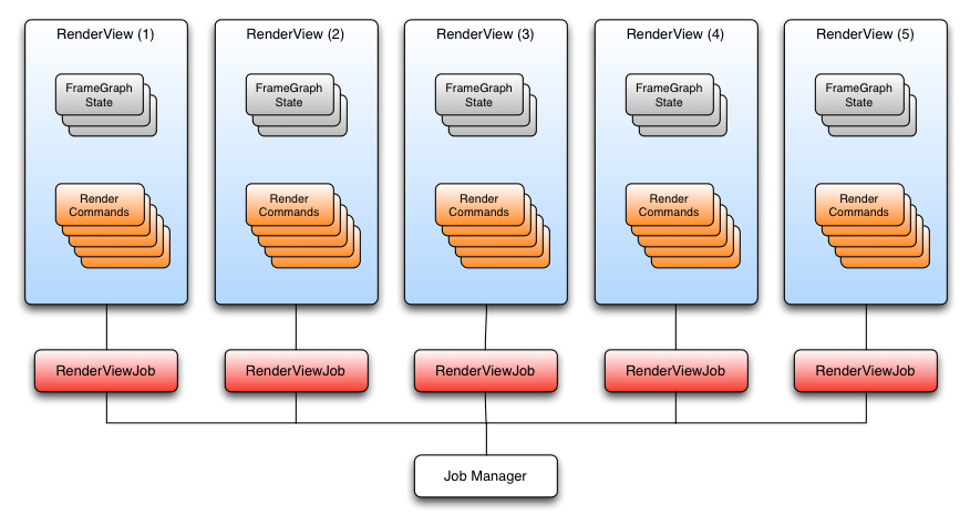
The RenderCommands for the RenderViews can be generated in parallel across many cores, and as long as we take care to submit the RenderViews in the correct order on the dedicated OpenGL submission thread, the resulting scene will be rendered correctly.
Deferred Renderer
When it comes to rendering, deferred rendering is a different beast in terms of renderer configuration compared to forward rendering. Instead of drawing each mesh and applying a shader effect to shade it, deferred rendering adopts a two render pass method.
First all the meshes in the scene are drawn using the same shader that will output, usually for each fragment, at least four values:
World normal vector
Color (or some other material properties)
Depth
World position vector
Each of these values will be stored in a texture. The normal, color, depth, and position textures form what is called the G-Buffer. Nothing is drawn onscreen during the first pass, but rather drawn into the G-Buffer ready for later use.
Once all the meshes have been drawn, the G-Buffer is filled with all the meshes that can currently be seen by the camera. The second render pass is then used to render the scene to the back buffer with the final color shading by reading the normal, color, and position values from the G-buffer textures and outputting a color onto a full screen quad.
The advantage of that technique is that the heavy computing power required for complex effects is only used during the second pass only on the elements that are actually being seen by the camera. The first pass does not cost much processing power as every mesh is being drawn with a simple shader. Deferred rendering, therefore, decouples shading and lighting from the number of objects in a scene and instead couples it to the resolution of the screen (and G-Buffer). This is a technique that has been used in many games due to the ability to use large numbers of dynamic lights at the expense of additional GPU memory usage.
(Above code is adapted from qt3d/tests/manual/deferred-renderer-qml.)
Graphically, the resulting framegraph looks like:
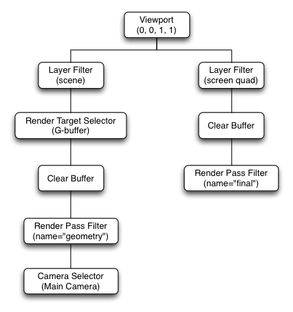
And the resulting RenderViews are:
RenderView (1)
Specify which camera should be used
Define a viewport that fills the whole screen
Select all Entities for layer component sceneLayer
Set the
gBufferas the active render targetClear the color and depth on the currently bound render target (the
gBuffer)Select only Entities in the scene that have a Material and Technique matching the annotations in the RenderPassFilter
RenderView (2)
Define a viewport that fills the whole screen
Select all Entities for layer component screenQuadLayer
Clear the color and depth buffers on the currently bound framebuffer (the screen)
Select only Entities in the scene that have a Material and Technique matching the annotations in the RenderPassFilter
Other Benefits of the framegraph
Since the FrameGraph tree is entirely data-driven and can be modified dynamically at runtime, you can:
Have different framegraph trees for different platforms and hardware and select the most appropriate at runtime
Easily add and enable visual debugging in a scene
Use different FrameGraph trees depending on the nature of what you need to render for a particular region of the scene
Implement a new rendering technique without having to modify Qt 3D’s internals
Conclusion
We have introduced the FrameGraph and the node types that compose it. We then went on to discuss a few examples to illustrate the framegraph building rules and how the Qt 3D engine uses the framegraph behind the scenes. By now you should have a pretty good overview of the FrameGraph and how it can be used (perhaps to add an early z-fill pass to a forward renderer). Also you should always keep in mind that the FrameGraph is a tool for you to use so that you are not tied down to the provided renderer and materials that Qt 3D provides out of the box.