Coordinate System
The coordinate system is controlled by the QPainter class. Together with the QPaintDevice and QPaintEngine classes, QPainter form the basis of Qt's painting system, Arthur. QPainter is used to perform drawing operations, QPaintDevice is an abstraction of a two-dimensional space that can be painted on using a QPainter, and QPaintEngine provides the interface that the painter uses to draw onto different types of devices.
The QPaintDevice class is the base class of objects that can be painted: Its drawing capabilities are inherited by the QWidget, QImage, QPixmap, QPicture, and QOpenGLPaintDevice classes. The default coordinate system of a paint device has its origin at the top-left corner. The x values increase to the right and the y values increase downwards. The default unit is one pixel on pixel-based devices and one point (1/72 of an inch) on printers.
The mapping of the logical QPainter coordinates to the physical QPaintDevice coordinates are handled by QPainter's transformation matrix, viewport and "window". The logical and physical coordinate systems coincide by default. QPainter also supports coordinate transformations (e.g. rotation and scaling).
Rendering
Logical Representation
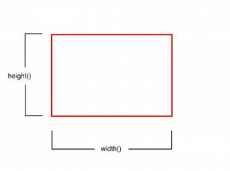
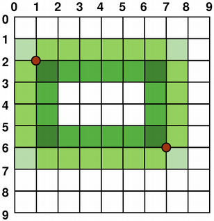
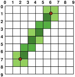
The size (width and height) of a graphics primitive always correspond to its mathematical model, ignoring the width of the pen it is rendered with:
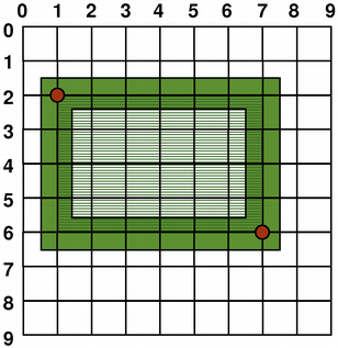 | 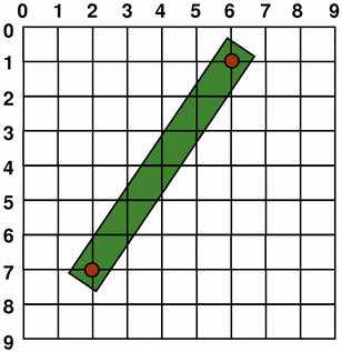 |
| QRect(QPoint(1, 2), QPoint(7, 6)) | QLine(QPoint(2, 7), QPoint(6, 1)) |
| QLine(2, 7, 6, 1) | |
| QRect(QPoint(1, 2), QSize(6, 4)) | |
| QRect(1, 2, 6, 4) |
Aliased Painting
When drawing, the pixel rendering is controlled by the QPainter::Antialiasing render hint.
The RenderHint enum is used to specify flags to QPainter that may or may not be respected by any given engine. The QPainter::Antialiasing value indicates that the engine should antialias edges of primitives if possible, i.e. smoothing the edges by using different color intensities.
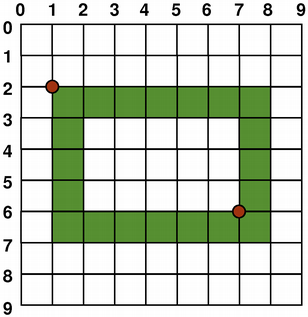
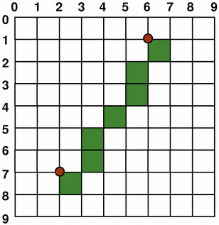
But by default the painter is aliased and other rules apply: When rendering with a one pixel wide pen the pixels will be rendered to the right and below the mathematically defined points. For example:
 |  |
When rendering with a pen with an even number of pixels, the pixels will be rendered symetrically around the mathematical defined points, while rendering with a pen with an odd number of pixels, the spare pixel will be rendered to the right and below the mathematical point as in the one pixel case. See the QRectF diagrams below for concrete examples.
| QRectF | |
|---|---|
 |  |
| Logical representation | One pixel wide pen |
 |  |
| Two pixel wide pen | Three pixel wide pen |
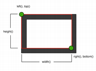
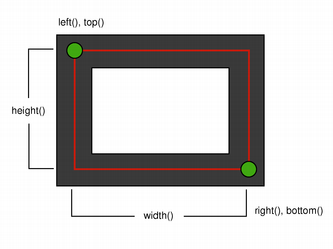
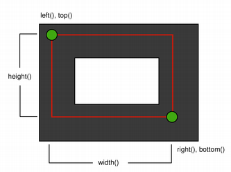
Note that for historical reasons the return value of the QRect::right() and QRect::bottom() functions deviate from the true bottom-right corner of the rectangle.
QRect's right() function returns left() + width() - 1 and the bottom() function returns top() + height() - 1. The bottom-right green point in the diagrams shows the return coordinates of these functions.
We recommend that you simply use QRectF instead: The QRectF class defines a rectangle in the plane using floating point coordinates for accuracy (QRect uses integer coordinates), and the QRectF::right() and QRectF::bottom() functions do return the true bottom-right corner.
Alternatively, using QRect, apply x() + width() and y() + height() to find the bottom-right corner, and avoid the right() and bottom() functions.
Anti-aliased Painting
If you set QPainter's anti-aliasing render hint, the pixels will be rendered symetrically on both sides of the mathematically defined points:
 |  |
Transformations
By default, the QPainter operates on the associated device's own coordinate system, but it also has complete support for affine coordinate transformations.
You can scale the coordinate system by a given offset using the QPainter::scale() function, you can rotate it clockwise using the QPainter::rotate() function and you can translate it (i.e. adding a given offset to the points) using the QPainter::translate() function.
You can also twist the coordinate system around the origin using the QPainter::shear() function. All the transformation operations operate on QPainter's transformation matrix that you can retrieve using the QPainter::worldTransform() function. A matrix transforms a point in the plane to another point.
If you need the same transformations over and over, you can also use QTransform objects and the QPainter::worldTransform() and QPainter::setWorldTransform() functions. You can at any time save the QPainter's transformation matrix by calling the QPainter::save() function which saves the matrix on an internal stack. The QPainter::restore() function pops it back.
One frequent need for the transformation matrix is when reusing the same drawing code on a variety of paint devices. Without transformations, the results are tightly bound to the resolution of the paint device. Printers have high resolution, e.g. 600 dots per inch, whereas screens often have between 72 and 100 dots per inch.
| Analog Clock Example | |
|---|---|
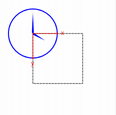
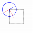
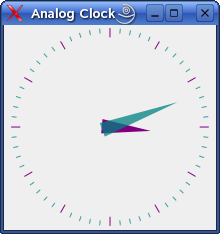 | The Analog Clock example shows how to draw the contents of a custom widget using QPainter's transformation matrix. We recommend compiling and running this example before you read any further. In particular, try resizing the window to different sizes. |
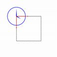
void AnalogClockWindow::render(QPainter *p)
{
    static const QPoint hourHand[3] = {
        QPoint(7, 8),
        QPoint(-7, 8),
        QPoint(0, -40)
    };
    static const QPoint minuteHand[3] = {
        QPoint(7, 8),
        QPoint(-7, 8),
        QPoint(0, -70)
    };

    QColor hourColor(127, 0, 127);
    QColor minuteColor(0, 127, 127, 191);

    p->setRenderHint(QPainter::Antialiasing);
    p->translate(width() / 2, height() / 2);

    int side = qMin(width(), height());
    p->scale(side / 200.0, side / 200.0);
We translate the coordinate system so that point (0, 0) is in the widget's center, instead of being at the top-left corner. We also scale the system by This will give us a 200 x 200 square area, with the origin (0, 0) in the center, that we can draw on. What we draw will show up in the largest possible square that will fit in the widget. See also the Window-Viewport Conversion section. QTime time = QTime::currentTime(); p->save(); p->rotate(30.0 * ((time.hour() + time.minute() / 60.0))); p->drawConvexPolygon(hourHand, 3); p->restore(); We draw the clock's hour hand by rotating the coordinate system and calling QPainter::drawConvexPolygon(). Thank's to the rotation, it's drawn pointed in the right direction. The polygon is specified as an array of alternating x, y values, stored in the The calls to QPainter::save() and QPainter::restore() surrounding the code guarantees that the code that follows won't be disturbed by the transformations we've used. p->save(); p->rotate(6.0 * (time.minute() + time.second() / 60.0)); p->drawConvexPolygon(minuteHand, 3); p->restore(); We do the same for the clock's minute hand, which is defined by the four points (1, 0), (0, 1), (-1, 0), and (0, -40). These coordinates specify a hand that is thinner and longer than the minute hand. p->setPen(minuteColor); for (int j = 0; j < 60; ++j) { if ((j % 5) != 0) p->drawLine(92, 0, 96, 0); p->rotate(6.0); } Finally, we draw the clock face, which consists of twelve short lines at 30-degree intervals. At the end of that, the painter is rotated in a way which isn't very useful, but we're done with painting so that doesn't matter. | |
For more information about the transformation matrix, see the QTransform documentation.
Window-Viewport Conversion
When drawing with QPainter, we specify points using logical coordinates which then are converted into the physical coordinates of the paint device.
The mapping of the logical coordinates to the physical coordinates are handled by QPainter's world transformation worldTransform() (described in the Transformations section), and QPainter's viewport() and window(). The viewport represents the physical coordinates specifying an arbitrary rectangle. The "window" describes the same rectangle in logical coordinates. By default the logical and physical coordinate systems coincide, and are equivalent to the paint device's rectangle.
Using window-viewport conversion you can make the logical coordinate system fit your preferences. The mechanism can also be used to make the drawing code independent of the paint device. You can, for example, make the logical coordinates extend from (-50, -50) to (50, 50) with (0, 0) in the center by calling the QPainter::setWindow() function:
Now, the logical coordinates (-50,-50) correspond to the paint device's physical coordinates (0, 0). Independent of the paint device, your painting code will always operate on the specified logical coordinates.
By setting the "window" or viewport rectangle, you perform a linear transformation of the coordinates. Note that each corner of the "window" maps to the corresponding corner of the viewport, and vice versa. For that reason it normally is a good idea to let the viewport and "window" maintain the same aspect ratio to prevent deformation:
int side = qMin(width(), height())
int x = (width() - side / 2);
int y = (height() - side / 2);

painter.setViewport(x, y, side, side);
If we make the logical coordinate system a square, we should also make the viewport a square using the QPainter::setViewport() function. In the example above we make it equivalent to the largest square that fit into the paint device's rectangle. By taking the paint device's size into consideration when setting the window or viewport, it is possible to keep the drawing code independent of the paint device.
Note that the window-viewport conversion is only a linear transformation, i.e. it does not perform clipping. This means that if you paint outside the currently set "window", your painting is still transformed to the viewport using the same linear algebraic approach.
![]()
The viewport, "window" and transformation matrix determine how logical QPainter coordinates map to the paint device's physical coordinates. By default the world transformation matrix is the identity matrix, and the "window" and viewport settings are equivalent to the paint device's settings, i.e. the world, "window" and device coordinate systems are equivalent, but as we have seen, the systems can be manipulated using transformation operations and window-viewport conversion. The illustration above describes the process.
See also Analog Clock Window Example.
© 2024 The Qt Company Ltd. Documentation contributions included herein are the copyrights of their respective owners. The documentation provided herein is licensed under the terms of the GNU Free Documentation License version 1.3 as published by the Free Software Foundation. Qt and respective logos are trademarks of The Qt Company Ltd. in Finland and/or other countries worldwide. All other trademarks are property of their respective owners.
