
モデルデータの使用
注:これは 「ウィジェット付きチャート ギャラリー」のサンプルの一部です。
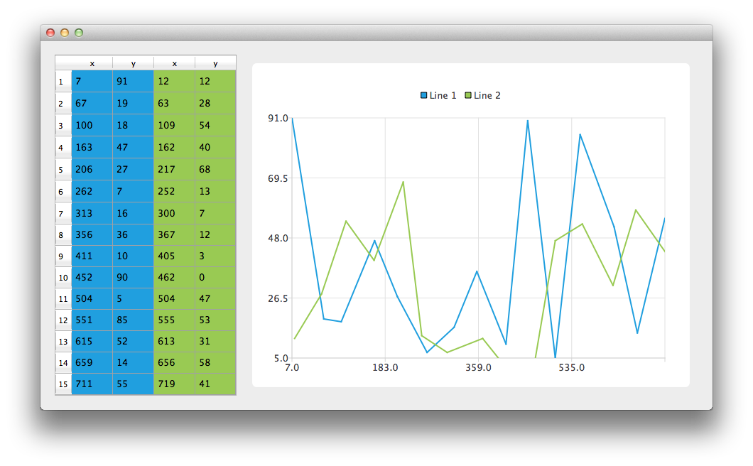
まず、CustomTableModel クラスのインスタンスを作成しましょう。CustomTableModel クラスは `QAbstractTableModel ` を継承しており、この例の目的のために作成されました。このクラスのコンストラクタは、チャート例に適したデータをモデルの内部データストアに格納します。
auto *model = new ModelDataModel;これで、チャートとQTableView の両方に表示したいデータを含むモデルができました。まず、QTableView を作成し、このモデルをデータソースとして使用するように指定します。データセルがテーブルビュー全体に広がるようにするため、ヘッダーのサイズ変更モードも変更します。
// create table view and add model to it
auto tableView = new QTableView;
tableView->setModel(model);
tableView->horizontalHeader()->setSectionResizeMode(QHeaderView::Stretch);
tableView->verticalHeader()->setSectionResizeMode(QHeaderView::Stretch);
次に、チャート上に同じデータを表示するための QChart インスタンスが必要です。また、アニメーションも有効にします。これにより、モデルのデータを変更した際にチャートにどのような影響が出るかをより分かりやすく確認できます。
以下のコードは、新しい線グラフシリーズを作成し、名前を付けます。次の行では、QVXYModelMapperクラスのインスタンスを作成します。 次の2行では、X座標をモデルのインデックス0の列(Qt::Vertical )から取得するように指定しています。Y座標はモデルのインデックス1の列から取得します。シリーズとモデルの間に関連付けを行うため、これら2つのオブジェクトをQVXYModelMapperに設定します。
最後に、シリーズをチャートに追加します。
auto series = new QLineSeries;
series->setName("Line 1");
auto mapper = new QVXYModelMapper(this);
mapper->setXColumn(0);
mapper->setYColumn(1);
mapper->setSeries(series);
mapper->setModel(model);
chart->addSeries(series);
QTableView 上で、どのデータがどの系列に対応しているかを示すため、この例ではテーブルの色分けを使用しています。系列がチャートに追加されると、現在選択されているテーマに基づいて色が割り当てられます。以下のコードは、その色を系列から抽出し、それを使用して色付きの `QTableView` を作成します。ビューの色付けは、QChart の機能の一部ではありません。
// for storing color hex from the series
QString seriesColorHex = "#000000";

// get the color of the series and use it for showing the mapped area
seriesColorHex = "#" + QString::number(series->pen().color().rgb(), 16).right(6).toUpper();
model->addMapping(seriesColorHex, QRect(0, 0, 2, model->rowCount()));
2つ目の系列に対しても同様の処理が行われます。この系列では、同じモデルの異なる列がマッピングされている点に注意してください。
series = new QLineSeries;
series->setName("Line 2");

mapper = new QVXYModelMapper(this);
mapper->setXColumn(2);
mapper->setYColumn(3);
mapper->setSeries(series);
mapper->setModel(model);
chart->addSeries(series);
// get the color of the series and use it for showing the mapped area
seriesColorHex = "#" + QString::number(series->pen().color().rgb(), 16).right(6).toUpper();
model->addMapping(seriesColorHex, QRect(2, 0, 2, model->rowCount()));
QGraphicsScene の設定作業を省くため、代わりにその設定を自動的に行ってくれるQChartViewクラスを使用します。QChartオブジェクトのポインタを、QChartViewコンストラクタのパラメータとして使用します。チャートの見栄えを良くするため、アンチエイリアシングを有効にし、chartViewウィジェットの最小サイズを設定します。
chart->createDefaultAxes();
chart->layout()->setContentsMargins(0, 0, 0, 0);
auto chartView = new QChartView(chart, this);
chartView->setRenderHint(QPainter::Antialiasing);
最後に、両方のウィジェットをレイアウトに配置し、そのレイアウトをアプリケーションのレイアウトとして使用します。
// create main layout
auto mainLayout = new QGridLayout;
mainLayout->addWidget(tableView, 1, 0);
mainLayout->addWidget(chartView, 1, 1);
mainLayout->setColumnStretch(1, 1);
mainLayout->setColumnStretch(0, 0);
setLayout(mainLayout);
これでアプリケーションの準備は完了です。テーブルビューのデータを変更してみて、チャートにどのような影響が出るか確認してみてください。
© 2026 The Qt Company Ltd. Documentation contributions included herein are the copyrights of their respective owners. The documentation provided herein is licensed under the terms of the GNU Free Documentation License version 1.3 as published by the Free Software Foundation. Qt and respective logos are trademarks of The Qt Company Ltd. in Finland and/or other countries worldwide. All other trademarks are property of their respective owners.
