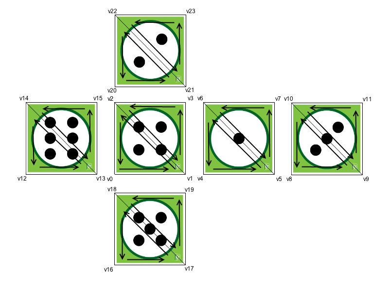
立方体 OpenGL ES 2.0 示例
展示如何通过用户输入手动旋转纹理 3D 立方体。
Cube OpenGL ES 2.0 示例展示了如何使用 Qt OpenGL ES 2.0 通过用户输入手动旋转纹理 3D 立方体。它展示了如何高效处理多边形几何图形,以及如何为可编程图形流水线编写简单的顶点和片段着色器。此外,它还展示了如何使用四元数来表示 3D 物体方向。
本示例是为 OpenGL ES 2.0 编写的,但也适用于桌面 OpenGL,因为本示例足够简单,而且大部分桌面 OpenGL API 都是一样的。它也可以在不支持 OpenGL 的情况下编译,但只会显示一个标签,说明需要 OpenGL 支持。

该示例由两个类组成:
MainWidget扩展QOpenGLWidget ,包含 OpenGL ES 2.0 初始化、绘图、鼠标和计时器事件处理。GeometryEngine处理多边形几何图形。将多边形几何图形传输到顶点缓冲区对象,并从顶点缓冲区对象绘制几何图形。
我们将首先在MainWidget 中初始化 OpenGL ES 2.0。
初始化 OpenGL ES 2.0
由于 OpenGL ES 2.0 不再支持固定的图形管道,因此必须由我们自己来实现。这使得图形管道非常灵活,但同时也变得更加困难,因为用户必须实现图形管道才能运行最简单的示例。这也使得图形管道更加高效,因为用户可以决定应用需要哪种管道。
首先,我们必须实现顶点着色器。它获取顶点数据和模型-视图-投影矩阵(MVP)作为参数。它使用 MVP 矩阵将顶点位置转换到屏幕空间,并将纹理坐标传递给片段着色器。纹理坐标将自动插值到多边形面上。
void main()
{
    // Calculate vertex position in screen space
    gl_Position = mvp_matrix * a_position;

    // Pass texture coordinate to fragment shader
    // Value will be automatically interpolated to fragments inside polygon faces
    v_texcoord = a_texcoord;
}
之后,我们需要实现图形管道的第二部分--片段着色器。在本练习中,我们需要实现处理纹理的片段着色器。它将内插纹理坐标作为参数,并从给定的纹理中查找片段颜色。
void main()
{
    // Set fragment color from texture
    gl_FragColor = texture2D(texture, v_texcoord);
}使用QOpenGLShaderProgram ,我们可以将着色器代码编译、链接并绑定到图形流水线。该代码使用 Qt 资源文件访问着色器源代码。
void MainWidget::initShaders()
{
    // Compile vertex shader
    if (!program.addShaderFromSourceFile(QOpenGLShader::Vertex, ":/vshader.glsl"))
        close();

    // Compile fragment shader
    if (!program.addShaderFromSourceFile(QOpenGLShader::Fragment, ":/fshader.glsl"))
        close();

    // Link shader pipeline
    if (!program.link())
        close();

    // Bind shader pipeline for use
    if (!program.bind())
        close();
}
以下代码启用了深度缓冲和背面剔除功能。
    // Enable depth buffer
    glEnable(GL_DEPTH_TEST);

    // Enable back face culling
    glEnable(GL_CULL_FACE);
从 Qt 资源文件加载纹理
QOpenGLWidget 接口实现了将纹理从QImage 加载到 OpenGL 纹理内存的方法。我们仍然需要使用 OpenGL 提供的函数来指定 OpenGL 纹理单元和配置纹理过滤选项。
void MainWidget::initTextures()
{
    // Load cube.png image
    texture = new QOpenGLTexture(QImage(":/cube.png").flipped());

    // Set nearest filtering mode for texture minification
    texture->setMinificationFilter(QOpenGLTexture::Nearest);

    // Set bilinear filtering mode for texture magnification
    texture->setMagnificationFilter(QOpenGLTexture::Linear);

    // Wrap texture coordinates by repeating
    // f.ex. texture coordinate (1.1, 1.2) is same as (0.1, 0.2)
    texture->setWrapMode(QOpenGLTexture::Repeat);
}
立方体几何图形
在 OpenGL 中渲染多边形的方法有很多,但最有效的方法是只使用三角形条状基元,并从图形硬件内存中渲染顶点。OpenGL 有一种机制,可为该内存区域创建缓冲对象,并将顶点数据传输到这些缓冲区。在 OpenGL 术语中,这些对象被称为顶点缓冲对象(VBO)。

立方体面就是这样分解成三角形的。顶点以这种方式排序是为了使用三角形条带获得正确的顶点排序。OpenGL 根据顶点排序确定三角形的前后面。默认情况下,OpenGL 对正面使用逆时针排序。背面剔除会使用这一信息,通过不渲染三角形的背面来提高渲染性能。这样,图形管道就可以省略渲染三角形中不面向屏幕的面。
使用QOpenGLBuffer 创建顶点缓冲区对象并向其传输数据非常简单。MainWidget 确保在创建和销毁 GeometryEngine 实例时使用当前的 OpenGL 上下文。这样,我们就可以在构造函数中使用 OpenGL 资源,并在析构函数中执行适当的清理。
GeometryEngine::GeometryEngine()
    : indexBuf(QOpenGLBuffer::IndexBuffer)
{
    initializeOpenGLFunctions();

    // Generate 2 VBOs
    arrayBuf.create();
    indexBuf.create();

    // Initializes cube geometry and transfers it to VBOs
    initCubeGeometry();
}

GeometryEngine::~GeometryEngine()
{
    arrayBuf.destroy();
    indexBuf.destroy();
}
    // Transfer vertex data to VBO 0
    arrayBuf.bind();
    arrayBuf.allocate(vertices, 24 * sizeof(VertexData));

    // Transfer index data to VBO 1
    indexBuf.bind();
    indexBuf.allocate(indices, 34 * sizeof(GLushort));
从 VBO 绘制基元并告诉可编程图形流水线如何定位顶点数据需要几个步骤。首先,我们需要绑定要使用的 VBO。然后,我们绑定着色器程序的属性名称,并配置绑定的 VBO 中的数据类型。最后,我们将使用另一个 VBO 中的索引绘制三角形条状基元。
void GeometryEngine::drawCubeGeometry(QOpenGLShaderProgram *program)
{
    // Tell OpenGL which VBOs to use
    arrayBuf.bind();
    indexBuf.bind();

    // Offset for position
    quintptr offset = 0;

    // Tell OpenGL programmable pipeline how to locate vertex position data
    int vertexLocation = program->attributeLocation("a_position");
    program->enableAttributeArray(vertexLocation);
    program->setAttributeBuffer(vertexLocation, GL_FLOAT, offset, 3, sizeof(VertexData));

    // Offset for texture coordinate
    offset += sizeof(QVector3D);

    // Tell OpenGL programmable pipeline how to locate vertex texture coordinate data
    int texcoordLocation = program->attributeLocation("a_texcoord");
    program->enableAttributeArray(texcoordLocation);
    program->setAttributeBuffer(texcoordLocation, GL_FLOAT, offset, 2, sizeof(VertexData));

    // Draw cube geometry using indices from VBO 1
    glDrawElements(GL_TRIANGLE_STRIP, 34, GL_UNSIGNED_SHORT, nullptr);
}
透视投影
使用QMatrix4x4 辅助方法,可以轻松计算透视投影矩阵。该矩阵用于将顶点投影到屏幕空间。
void MainWidget::resizeGL(int w, int h)
{
    // Calculate aspect ratio
    qreal aspect = qreal(w) / qreal(h ? h : 1);

    // Set near plane to 3.0, far plane to 7.0, field of view 45 degrees
    const qreal zNear = 3.0, zFar = 7.0, fov = 45.0;

    // Reset projection
    projection.setToIdentity();

    // Set perspective projection
    projection.perspective(fov, aspect, zNear, zFar);
}
3D 物体的方向
四元数是表示 3D 物体方向的便捷方法。四元数涉及相当复杂的数学,但幸运的是,四元数背后所有必要的数学都在QQuaternion 中实现。这样,我们就可以用四元数存储立方体的方向,围绕给定轴线旋转立方体也就非常简单了。
以下代码根据鼠标事件计算旋转轴和角速度。
void MainWidget::mousePressEvent(QMouseEvent *e)
{
    // Save mouse press position
    mousePressPosition = QVector2D(e->position());
}

void MainWidget::mouseReleaseEvent(QMouseEvent *e)
{
    // Mouse release position - mouse press position
    QVector2D diff = QVector2D(e->position()) - mousePressPosition;

    // Rotation axis is perpendicular to the mouse position difference
    // vector
    QVector3D n = QVector3D(diff.y(), diff.x(), 0.0).normalized();

    // Accelerate angular speed relative to the length of the mouse sweep
    qreal acc = diff.length() / 100.0;

    // Calculate new rotation axis as weighted sum
    rotationAxis = (rotationAxis * angularSpeed + n * acc).normalized();

    // Increase angular speed
    angularSpeed += acc;
}
QBasicTimer 旋转轴和角度速度用于制作场景动画和更新立方体方向。旋转可以通过简单的四元数乘法串联起来。
void MainWidget::timerEvent(QTimerEvent *)
{
    // Decrease angular speed (friction)
    angularSpeed *= 0.99;

    // Stop rotation when speed goes below threshold
    if (angularSpeed < 0.01) {
        angularSpeed = 0.0;
    } else {
        // Update rotation
        rotation = QQuaternion::fromAxisAndAngle(rotationAxis, angularSpeed) * rotation;

        // Request an update
        update();
    }
}
模型视图矩阵是通过四元数和 Z 轴移动世界来计算的。该矩阵与投影矩阵相乘,即可得到着色器程序的 MVP 矩阵。
    // Calculate model view transformation
    QMatrix4x4 matrix;
    matrix.translate(0.0, 0.0, -5.0);
    matrix.rotate(rotation);

    // Set modelview-projection matrix
    program.setUniformValue("mvp_matrix", projection * matrix);
© 2025 The Qt Company Ltd. Documentation contributions included herein are the copyrights of their respective owners. The documentation provided herein is licensed under the terms of the GNU Free Documentation License version 1.3 as published by the Free Software Foundation. Qt and respective logos are trademarks of The Qt Company Ltd. in Finland and/or other countries worldwide. All other trademarks are property of their respective owners.

