
Qt Quick 3D Physics - Exemple de formes composées
Démonstration de l'utilisation de formes de collision complexes.
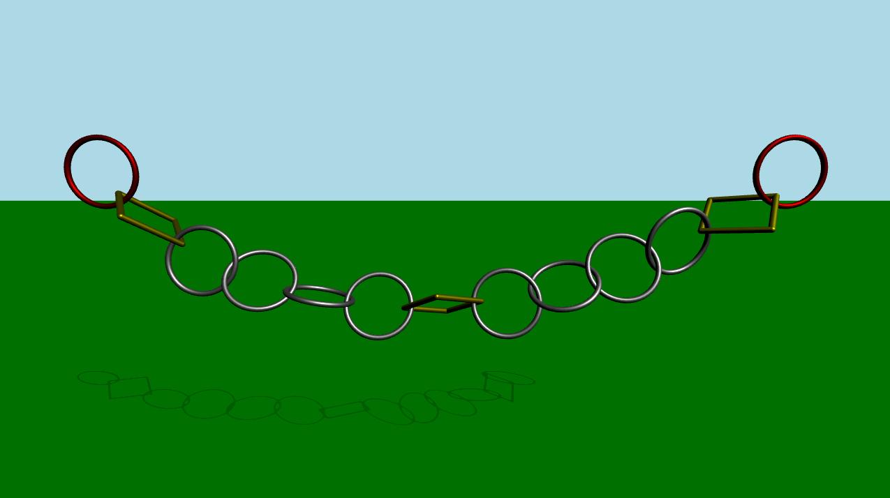
Cet exemple montre comment utiliser plusieurs formes de collision pour créer des objets complexes en vue de la détection des collisions. La scène se compose d'un plan statique vert et d'une série de maillons reliés entre eux. Au début, la simulation est désactivée. Après un certain temps ou lorsque l'utilisateur appuie sur la touche espace, la simulation démarre. Une animation se lancera, provoquant un mouvement horizontal de va-et-vient des maillons situés à l'extrême gauche et à l'extrême droite.
Configuration
Comme d’habitude, nous devons ajouter notre projet « PhysicsWorld » :
PhysicsWorld {
    id: physicsWorld
    enableCCD: true
    maximumTimestep: 20
    scene: viewport.scene
}
Nous procédons à la configuration habituelle comprenant un environnement, une caméra et des lumières :
environment: SceneEnvironment {
    antialiasingMode: SceneEnvironment.MSAA
    backgroundMode: SceneEnvironment.Color
    clearColor: "lightblue"
}

focus: true

PerspectiveCamera {
    id: camera
    position: Qt.vector3d(0, 900, 1500)
    eulerRotation: Qt.vector3d(-10, 0, 0)
    clipFar: 15500
    clipNear: 1
}

DirectionalLight {
    eulerRotation.x: -45
    eulerRotation.y: 45
    castsShadow: true
    brightness: 1.5
    shadowMapQuality: Light.ShadowMapQualityHigh
}
Objets physiques
Nous disposons de notre plan statique habituel :
StaticRigidBody {
    position: Qt.vector3d(0, -100, 0)
    eulerRotation: Qt.vector3d(-90, 0, 0)
    collisionShapes: PlaneShape {}
    Model {
        source: "#Rectangle"
        scale: Qt.vector3d(500, 500, 1)
        materials: PrincipledMaterial {
            baseColor: "green"
        }
        castsShadows: false
        receivesShadows: true
    }
}
Ensuite, nous créons des instances de nos liaisons.
MeshLink {
    id: leftLink
    isKinematic: true
    property vector3d startPos: Qt.vector3d(-6 * viewport.ringDistance,
                                            viewport.ringY,
                                            0)
    property vector3d startRot: Qt.vector3d(90, 0, 0)
    kinematicPosition: startPos
    position: startPos
    kinematicEulerRotation: startRot
    eulerRotation: startRot
    color: "red"
}

CapsuleLink {
    position: Qt.vector3d(-5 * viewport.ringDistance, viewport.ringY, 0)
    eulerRotation: Qt.vector3d(90, 0, 0)
}

MeshLink {
    position: Qt.vector3d(-4 * viewport.ringDistance, viewport.ringY, 0)
    eulerRotation: Qt.vector3d(90, 0, 0)
}

MeshLink {
    position: Qt.vector3d(-3 * viewport.ringDistance, viewport.ringY, 0)
    eulerRotation: Qt.vector3d(0, 90, 0)
}

MeshLink {
    position: Qt.vector3d(-2 * viewport.ringDistance, viewport.ringY, 0)
    eulerRotation: Qt.vector3d(90, 0, 0)
}

MeshLink {
    position: Qt.vector3d(-1 * viewport.ringDistance, viewport.ringY, 0)
    eulerRotation: Qt.vector3d(0, 90, 0)
}

CapsuleLink {
    position: Qt.vector3d(0, viewport.ringY, 0)
}

MeshLink {
    position: Qt.vector3d(1 * viewport.ringDistance, viewport.ringY, 0)
    eulerRotation: Qt.vector3d(0, 90, 0)
}

MeshLink {
    position: Qt.vector3d(2 * viewport.ringDistance, viewport.ringY, 0)
    eulerRotation: Qt.vector3d(90, 0, 0)
}

MeshLink {
    position: Qt.vector3d(3 * viewport.ringDistance, viewport.ringY, 0)
    eulerRotation: Qt.vector3d(0, 90, 0)
}

MeshLink {
    position: Qt.vector3d(4 * viewport.ringDistance, viewport.ringY, 0)
    eulerRotation: Qt.vector3d(90, 0, 0)
}

CapsuleLink {
    position: Qt.vector3d(5 * viewport.ringDistance, viewport.ringY, 0)
    eulerRotation: Qt.vector3d(90, 0, 0)
}

MeshLink {
    id: rightLink
    isKinematic: true
    property vector3d startPos: Qt.vector3d(6 * viewport.ringDistance,
                                            viewport.ringY,
                                            0)
    property vector3d startRot: Qt.vector3d(90, 0, 0)
    kinematicPosition: startPos
    position: startPos
    kinematicEulerRotation: startRot
    eulerRotation: startRot
    color: "red"
}
Le premier maillon, situé à gauche, a sa propriété « isKinematic » définie sur « true » afin que nous puissions le contrôler via une animation. Comme il s’agit d’un objet cinématique, nous devons définir les propriétés « kinematicPosition » et « kinematicRotation ». Nous l’animons en animant la propriété « kinematicPosition ». Les autres maillons sont instanciés avec un certain espacement entre eux.
Pour obtenir une animation fluide qui suive exactement la simulation physique, nous utilisons un « AnimationController » que nous connectons au signal « onFrameDone » de la propriété « PhysicsWorld ». De cette manière, s’il venait à y avoir des pertes d’images ralentissant la simulation, l’animation ralentirait en conséquence. Nous utilisons un « SequentialAnimation » avec quatre « NumberAnimation » pour faire aller et venir les anneaux situés à l’extrême gauche et à l’extrême droite. Voici le code QML de l’animation :
Connections {
    target: physicsWorld
    property real totalAnimationTime: 12000
    function onFrameDone(timeStep) {
        let progressStep = timeStep / totalAnimationTime
        animationController.progress += progressStep
        if (animationController.progress >= 1) {
            animationController.completeToEnd()
            animationController.reload()
            animationController.progress = 0
        }
    }
}

AnimationController {
    id: animationController
    animation: SequentialAnimation {
        NumberAnimation {
            target: leftLink
            property: "kinematicPosition.x"
            to: 3 * viewport.ringDistance
            from: -6 * viewport.ringDistance
            easing.type: Easing.InOutCubic
            duration: 1000
        }
        NumberAnimation {
            target: leftLink
            property: "kinematicPosition.x"
            from: 3 * viewport.ringDistance
            to: -6 * viewport.ringDistance
            easing.type: Easing.InOutCubic
            duration: 1000
        }
        NumberAnimation {
            target: rightLink
            property: "kinematicPosition.x"
            to: -3 * viewport.ringDistance
            from: 6 * viewport.ringDistance
            easing.type: Easing.InOutCubic
            duration: 1000
        }
        NumberAnimation {
            target: rightLink
            property: "kinematicPosition.x"
            from: -3 * viewport.ringDistance
            to: 6 * viewport.ringDistance
            easing.type: Easing.InOutCubic
            duration: 1000
        }
    }
}
Ce qui est intéressant, c’est ce qui se passe à l’intérieur des fichiers Mesh Link et Capsule Link. Examinons-les un par un.
Lien Mesh
DynamicRigidBody {
    id: root
    scale: Qt.vector3d(100, 100, 100)
    property color color: "white"
    PrincipledMaterial {
        id: _material
        baseColor: root.color
        metalness: 1.0
        roughness: 0.5
    }

    Model {
        source: "meshes/ring.mesh"
        materials: [_material]
    }

    collisionShapes: [
        ConvexMeshShape {
            source: "meshes/segmentedRing_001.mesh"
        },
        ConvexMeshShape {
            source: "meshes/segmentedRing_002.mesh"
        },
        ConvexMeshShape {
            source: "meshes/segmentedRing_003.mesh"
        },
        ConvexMeshShape {
            source: "meshes/segmentedRing_004.mesh"
        },
        ConvexMeshShape {
            source: "meshes/segmentedRing_005.mesh"
        },
        ConvexMeshShape {
            source: "meshes/segmentedRing_006.mesh"
        },
        ConvexMeshShape {
            source: "meshes/segmentedRing_007.mesh"
        },
        ConvexMeshShape {
            source: "meshes/segmentedRing_008.mesh"
        },
        ConvexMeshShape {
            source: "meshes/segmentedRing_009.mesh"
        },
        ConvexMeshShape {
            source: "meshes/segmentedRing_010.mesh"
        },
        ConvexMeshShape {
            source: "meshes/segmentedRing_011.mesh"
        },
        ConvexMeshShape {
            source: "meshes/segmentedRing_012.mesh"
        }
    ]
}
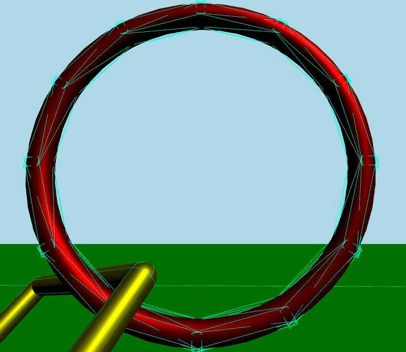
Le lien Mesh est un corps rigide dynamique doté d’un modèle et d’un matériau. Le modèle charge le maillage à partir d’un fichier de maillage. Nous disposons également d’une liste de formes de collision qui, une fois combinées, forment une forme composite pour la détection des collisions. Chaque forme est une forme « Convex Mesh » qui charge le maillage à partir d’un fichier source. Une forme convexe est essentiellement une forme dans laquelle la ligne reliant deux points quelconques à l’intérieur de la forme se trouve toujours à l’intérieur de celle-ci.
Si l’on y regarde de plus près lorsque le mode débogage est activé, voici comment les formes de collision forment la forme de collision composite :
Lien Capsule
DynamicRigidBody {
    id: root
    property real len: 170
    property real w: 17
    PrincipledMaterial {
        id: material3
        baseColor: "yellow"
        metalness: 1.0
        roughness: 0.5
    }
    Node {
        opacity: 1
        Model {
            materials: material3
            source: "#Cylinder"
            scale: Qt.vector3d(root.w / 100, root.len / 100, root.w / 100)
            eulerRotation.z: 90
            y: -root.len / 2
        }
        Model {
            materials: material3
            source: "#Cylinder"
            scale: Qt.vector3d(root.w / 100, root.len / 100, root.w / 100)
            eulerRotation.z: 90
            y: root.len / 2
        }
        Model {
            materials: material3
            source: "#Cylinder"
            scale: Qt.vector3d(root.w / 100, root.len / 100, root.w / 100)
            x: root.len / 2
        }
        Model {
            materials: material3
            source: "#Cylinder"
            scale: Qt.vector3d(root.w / 100, root.len / 100, root.w / 100)
            x: -root.len / 2
        }
        Model {
            materials: material3
            source: "#Sphere"
            scale: Qt.vector3d(root.w / 100, root.w / 100, root.w / 100)
            x: -root.len / 2
            y: -root.len / 2
        }
        Model {
            materials: material3
            source: "#Sphere"
            scale: Qt.vector3d(root.w / 100, root.w / 100, root.w / 100)
            x: -root.len / 2
            y: root.len / 2
        }
        Model {
            materials: material3
            source: "#Sphere"
            scale: Qt.vector3d(root.w / 100, root.w / 100, root.w / 100)
            x: root.len / 2
            y: -root.len / 2
        }
        Model {
            materials: material3
            source: "#Sphere"
            scale: Qt.vector3d(root.w / 100, root.w / 100, root.w / 100)
            x: root.len / 2
            y: root.len / 2
        }
    }
    collisionShapes: [
        CapsuleShape {
            y: -root.len / 2
            height: root.len
            diameter: root.w
        },
        CapsuleShape {
            y: root.len / 2
            height: root.len
            diameter: root.w
        },
        CapsuleShape {
            x: -root.len / 2
            eulerRotation.z: 90
            height: root.len
            diameter: root.w
        },
        CapsuleShape {
            x: root.len / 2
            eulerRotation.z: 90
            height: root.len
            diameter: root.w
        }
    ]
}
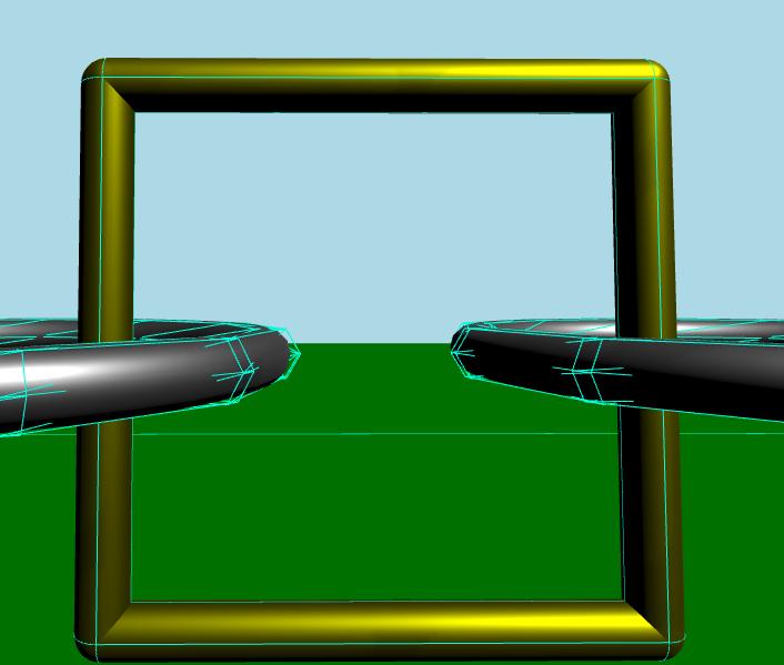
Le « Capsule Link » est un corps rigide dynamique composé de plusieurs modèles partageant le même matériau. Ce lien est constitué de plusieurs cylindres et sphères. À l’instar du « Mesh Link », il comporte une liste de formes de collision. Cette fois-ci, chaque forme est une « Capsule Shape ».
Si l’on y regarde de plus près lorsque le mode débogage est activé, voici comment les formes de collision forment la forme de collision composite.
Fichiers :
© 2026 The Qt Company Ltd. Documentation contributions included herein are the copyrights of their respective owners. The documentation provided herein is licensed under the terms of the GNU Free Documentation License version 1.3 as published by the Free Software Foundation. Qt and respective logos are trademarks of The Qt Company Ltd. in Finland and/or other countries worldwide. All other trademarks are property of their respective owners.
