
选定点配置
注意:这是 “带小部件的图表”示例库的一部分。
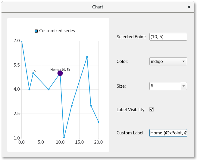
演示功能
在此您将学习如何:
- 为数据系列中的数据点提供点击选择功能。
- 覆盖特定数据点的单独配置,包括:
- 颜色
- 大小
- 标签的可见性
- 标签的文本格式
运行示例
您可以通过以下方式运行示例:
- Qt Creator
打开Welcome 模式,并从Examples 中选择该示例。有关更多信息,请参阅Qt Creator :教程:构建和运行。
- Qt Extension for Visual Studio Code
在Command Palette 中运行Qt: Open Qt examples 命令,然后从列表中选择示例。有关详细信息,请参阅Qt Extension for Visual Studio Code :教程:构建和运行。
继承 QMainWindow
首先,我们创建一个QMainWindow 的子类,该类将包含图表和控件。同时,我们提供构造函数实现的模板代码:
PointConfigurationWidget::PointConfigurationWidget(QWidget *parent)
    : ContentWidget(parent)
{
创建一条线形序列
接着,我们创建一个 QLineSeries 对象,为其指定名称,设置数据点可见,并提供一些数据点进行绘制。
m_series = new QLineSeries;
m_series->setPointsVisible(true);
m_series->append({QPointF(0, 7),  QPointF(2, 4),
                  QPointF(3, 5),  QPointF(7, 4),
                  QPointF(10, 5), QPointF(11, 1),
                  QPointF(13, 3), QPointF(17, 6),
                  QPointF(18, 3), QPointF(20, 2)});
创建数据点配置控件
现在,我们创建一些控件来配置点的数据颜色、大小、标签可见性以及标签本身。我们为每个控件创建一个关联标签,以便用户了解该控件的功能。
对于颜色和大小,我们使用QComboBox ,并为其提供多种颜色和大小选项。
接下来,我们创建最后两个控件。一个复选框用于控制所选点的可见性;另一个控件是QLineEdit ,允许用户为该点提供自定义标签。
请注意,我们未为任何控件设置初始值,因为系统始终会选中一个点并显示其当前设置。
auto selectedPointIndexLabel = new QLabel(tr("Selected Point: "), this);
m_selectedPointIndexLineEdit = new QLineEdit(this);
m_selectedPointIndexLineEdit->setReadOnly(true);

auto colorLabel = new QLabel(tr("Color: "), this);
m_colorCombobox = new QComboBox(this);
QStringList colorStrings = {"red", "orange", "yellow", "green", "blue",
                            "indigo", "violet", "black"};
QStringList trColorStrings = {tr("red"), tr("orange"), tr("yellow"),
                              tr("green"), tr("blue"), tr("indigo"),
                              tr("violet"), tr("black")};
for (int i = 0; i < colorStrings.size(); i++)
    m_colorCombobox->addItem(QIcon(), trColorStrings[i], QColor(colorStrings[i]));

auto sizeLabel = new QLabel(tr("Size: "), this);
m_sizeCombobox = new QComboBox(this);
for (auto size : { 2, 3, 4, 6, 8, 10, 12, 15 })
    m_sizeCombobox->addItem(QIcon(), QString::number(size), size);

auto labelVisibilityLabel = new QLabel(tr("Label Visibility: "), this);
m_labelVisibilityCheckbox = new QCheckBox(this);

auto customLabelLabel = new QLabel(tr("Custom Label: "), this);
m_customLabelLineEdit = new QLineEdit(this);
在选择点时填充控件
现在控件已就绪,我们需要编写逻辑代码,为选中的点设置当前控件值。请注意,如果选中的点没有自定义设置,则使用整个系列的默认值。例如,如果系列设置为显示蓝色点,则颜色下拉列表中将显示蓝色值。
点击折线图时,我们会查找被点击的数据点,清除之前的选点,然后选中被点击的数据点。这在图表上通过视觉效果标示选中的数据点——使该点变大以表明其已被选中。当前选中数据点的索引及其PointConfigurations 会被保存到成员变量中,以备后续使用。
查询PointConfigurations ,并在下拉列表中查找匹配的值,随后相应地设置下拉列表的当前索引。对于复选框和文本输入框,同样从PointConfigurations 中查找值,并将控件设置为与之匹配。
QObject::connect(m_series, &QXYSeries::clicked, m_series, [&](const QPointF &point) {
    int index = m_series->points().indexOf(point.toPoint());
    if (index != -1) {
        m_series->deselectAllPoints();
        m_series->selectPoint(index);
        m_selectedPointIndex = index;
        m_selectedPointConfig = m_series->pointConfiguration(index);
        const QPointF selectedPoint(m_series->at(index));
        m_selectedPointIndexLineEdit->setText("(" + QString::number(selectedPoint.x()) + ", " +
                                              QString::number(selectedPoint.y()) + ")");
        PointConfigurations config = m_series->pointConfiguration(index);

        QVariant colorVar = config[QXYSeries::PointConfiguration::Color];
        QColor color = colorVar.isValid() ? colorVar.value<QColor>() : m_series->color();
        if (m_colorCombobox->findData(color) < 0)
            m_colorCombobox->addItem(color.name(), color);
        m_colorCombobox->setCurrentIndex(m_colorCombobox->findData(color));

        QVariant sizeVar = config[QXYSeries::PointConfiguration::Size];
        qreal size = sizeVar.isValid() ? sizeVar.toReal() : m_series->markerSize();
        if (m_sizeCombobox->findData(size) < 0)
            m_sizeCombobox->addItem(QString::number(size), size);
        m_sizeCombobox->setCurrentIndex(m_sizeCombobox->findData(size));

        QVariant labelVisibilityVar = config[QXYSeries::PointConfiguration::LabelVisibility];
        bool labelVisibility = labelVisibilityVar.isValid() ? labelVisibilityVar.toBool() :
                                                              m_series->pointLabelsVisible();
        m_labelVisibilityCheckbox->setChecked(labelVisibility);

        QVariant customLabelVar = config[QXYSeries::PointConfiguration::LabelFormat];
        QString customLabel = customLabelVar.isValid() ? customLabelVar.toString() : "";
        m_customLabelLineEdit->setText(customLabel);
    }
});
提供配置所选点的逻辑
现在控件已加载了当前配置,我们需要让它们执行相应操作。我们将控件的信号连接到逻辑处理程序,该程序将根据所选设置对选定点进行配置。具体操作很简单:将控件关联的QXYSeries::PointConfiguration 值设置为m_selectedPointConfig 的PointConfigurations 成员变量,并调用QXYSeries::setPointConfiguration 。
QObject::connect(m_colorCombobox, &QComboBox::activated, m_series, [&](const int) {
    m_selectedPointConfig[QXYSeries::PointConfiguration::Color] = m_colorCombobox->currentData();
    m_series->setPointConfiguration(m_selectedPointIndex, m_selectedPointConfig);
});
QObject::connect(m_sizeCombobox, &QComboBox::activated, m_series, [&](const int) {
    m_selectedPointConfig[QXYSeries::PointConfiguration::Size] = m_sizeCombobox->currentData();
    m_series->setPointConfiguration(m_selectedPointIndex, m_selectedPointConfig);
});
QObject::connect(m_labelVisibilityCheckbox, &QAbstractButton::clicked, m_series, [&](const bool checked) {
    m_selectedPointConfig[QXYSeries::PointConfiguration::LabelVisibility] = checked;
    m_series->setPointConfiguration(m_selectedPointIndex, m_selectedPointConfig);
});
QObject::connect(m_customLabelLineEdit, &QLineEdit::editingFinished, m_series, [&]() {
    m_selectedPointConfig[QXYSeries::PointConfiguration::LabelFormat] = m_customLabelLineEdit->text();
    m_series->setPointConfiguration(m_selectedPointIndex, m_selectedPointConfig);
});
创建图表并布局控件
最后,我们创建图表及其视图,将数据系列添加到图表中,并设计窗口布局。作为此过程的一部分,我们会连接到geometryChanged 信号,以便在图表首次绘制时捕获该信号。这样可以确保初始选定点的数值正确。 如果我们提前进行此操作,数据点的数值将会不正确。该连接在首次触发后即会被断开。
auto chart = new QChart;
chart->addSeries(m_series);
chart->createDefaultAxes();
chart->setTitle("Select points with mouse click");
chart->layout()->setContentsMargins(0, 0, 0, 0);
chart->legend()->setVisible(false);

m_selectInitialPointConnection = QObject::connect(chart, &QChart::geometryChanged, chart, [&]() {
    m_series->selectPoint(4);
    m_series->clicked(m_series->at(m_series->selectedPoints()[0]));
    disconnect(m_selectInitialPointConnection);
});

auto chartView = new QChartView(chart, this);
chartView->setRenderHint(QPainter::Antialiasing);

auto controlWidget = new QWidget(this);
auto controlLayout = new QGridLayout(controlWidget);
controlLayout->setColumnStretch(1, 1);

controlLayout->addWidget(selectedPointIndexLabel, 0, 0);
controlLayout->addWidget(m_selectedPointIndexLineEdit, 0, 1);

controlLayout->addWidget(colorLabel, 1, 0);
controlLayout->addWidget(m_colorCombobox, 1, 1);

controlLayout->addWidget(sizeLabel, 2, 0);
controlLayout->addWidget(m_sizeCombobox, 2, 1);

controlLayout->addWidget(labelVisibilityLabel, 3, 0);
controlLayout->addWidget(m_labelVisibilityCheckbox, 3, 1, 1, 2);

controlLayout->addWidget(customLabelLabel, 4, 0);
controlLayout->addWidget(m_customLabelLineEdit, 4, 1);

auto mainLayout = new QHBoxLayout(this);
mainLayout->addWidget(chartView);
mainLayout->setStretch(0, 1);
mainLayout->addWidget(controlWidget);
现在,我们已经拥有了一个功能齐全的应用程序,它演示了如何自定义单个图表数据点。
© 2026 The Qt Company Ltd. Documentation contributions included herein are the copyrights of their respective owners. The documentation provided herein is licensed under the terms of the GNU Free Documentation License version 1.3 as published by the Free Software Foundation. Qt and respective logos are trademarks of The Qt Company Ltd. in Finland and/or other countries worldwide. All other trademarks are property of their respective owners.
