
QML示波器
本示例演示了如何使用Qt Charts QML API实现具有严格性能要求的应用程序。
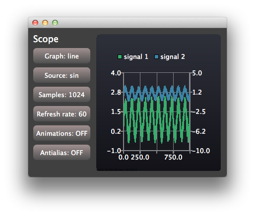
该示波器应用程序演示了如何使用Qt Charts QML API来实现一个具有严格性能要求的应用程序。该应用程序使用具有可配置特性的生成数据来模拟一个简单的示波器用户界面。
要获取应用程序输出控制台中显示的实际渲染速度信息,您可以在运行环境设置中将 QSG_RENDER_TIMING 设置为 1。 操作步骤:在Qt Creator 中依次选择“项目” - “运行” - “运行环境”,然后点击“添加”。随后,您可以尝试调整示例应用程序的各种可配置选项,以找出在您的环境中能提供最佳性能的配置。
运行示例
您可以通过以下方式运行示例:
- Qt Creator
打开Welcome 模式,并从“Examples ”中选择该示例。有关更多信息,请参阅Qt Creator :教程:构建和运行。
- Qt Extension for Visual Studio Code
在Command Palette 中运行Qt: Open Qt examples 命令,然后从列表中选择该示例。有关更多信息,请参阅Qt Extension for Visual Studio Code :教程:构建和运行。
创建视图
控制视图和范围视图共享应用程序窗口:
Item {
    id: main
    width: 600
    height: 400

    ControlPanel {
        id: controlPanel
        anchors.top: parent.top
        anchors.topMargin: 10
        anchors.bottom: parent.bottom
        anchors.left: parent.left
        anchors.leftMargin: 10
    ...
    ScopeView {
        id: scopeView
        anchors.top: parent.top
        anchors.bottom: parent.bottom
        anchors.right: parent.right
        anchors.left: controlPanel.right
        height: main.height
    }
ControlView 实现了用于配置的按钮。ScopeView 使用 ChartView 显示一个包含两条线系列的图表:
ChartView {
    id: chartView

    property bool openGL: openGLSupported

    animationOptions: ChartView.NoAnimation
    theme: ChartView.ChartThemeDark

    onOpenGLChanged: {
        if (openGLSupported) {
            var series1 = series("signal 1")
            if (series1)
                series1.useOpenGL = openGL;
            var series2 = series("signal 2")
            if (series2)
                series2.useOpenGL = openGL;
        }
    }

    ValueAxis {
        id: axisY1
        min: -1
        max: 4
    }

    ValueAxis {
        id: axisY2
        min: -10
        max: 5
    }

    ValueAxis {
        id: axisX
        min: 0
        max: 1024
    }

    LineSeries {
        id: lineSeries1
        name: "signal 1"
        axisX: axisX
        axisY: axisY1
        useOpenGL: chartView.openGL
    }
    LineSeries {
        id: lineSeries2
        name: "signal 2"
        axisX: axisX
        axisYRight: axisY2
        useOpenGL: chartView.openGL
    }
    ...
线性系列的数据通过 Qt Qml 定时器进行更新。在实际应用中,更新操作可通过 Qt C++ 代码发出的信号触发。
Timer {
    id: refreshTimer
    interval: 1 / 60 * 1000 // 60 Hz
    running: true
    repeat: true
    onTriggered: {
        dataSource.update(chartView.series(0));
        dataSource.update(chartView.series(1));
    }
}
示波器还允许您切换用于可视化信号源的系列类型。这是通过动态销毁和创建系列来实现的:
function changeSeriesType(type) {
    chartView.removeAllSeries();

    // Create two new series of the correct type. Axis x is the same for both of the series,
    // but the series have their own y-axes to make it possible to control the y-offset
    // of the "signal sources".
    var series1
    var series2
    if (type === "line") {
        series1 = chartView.createSeries(ChartView.SeriesTypeLine, "signal 1",
                                         axisX, axisY1);
        series1.useOpenGL = chartView.openGL

        series2 = chartView.createSeries(ChartView.SeriesTypeLine, "signal 2",
                                         axisX, axisY2);
        series2.useOpenGL = chartView.openGL
    } else {
        series1 = chartView.createSeries(ChartView.SeriesTypeScatter, "signal 1",
                                         axisX, axisY1);
        series1.markerSize = 2;
        series1.borderColor = "transparent";
        series1.useOpenGL = chartView.openGL

        series2 = chartView.createSeries(ChartView.SeriesTypeScatter, "signal 2",
                                         axisX, axisY2);
        series2.markerSize = 2;
        series2.borderColor = "transparent";
        series2.useOpenGL = chartView.openGL
    }
}

function createAxis(min, max) {
    // The following creates a ValueAxis object that can be then set as a x or y axis for a series
    return Qt.createQmlObject("import QtQuick 2.0; import QtCharts 2.0; ValueAxis { min: "
                              + min + "; max: " + max + " }", chartView);
}© 2026 The Qt Company Ltd. Documentation contributions included herein are the copyrights of their respective owners. The documentation provided herein is licensed under the terms of the GNU Free Documentation License version 1.3 as published by the Free Software Foundation. Qt and respective logos are trademarks of The Qt Company Ltd. in Finland and/or other countries worldwide. All other trademarks are property of their respective owners.
