
4.1. Architecture
4.1.1. Introduction
Here we cover the setup of the Axivion Suite for the purpose of erosion protection with regards to software architecture. You will learn about the three main inputs to the architecture analysis (namely the as-is system structure, the architecture and the mapping), how to create them and how to setup the architecture analysis process itself.
4.1.2. Architecture Analysis
Three aspects are needed for setting up an architecture check. Each aspect is represented by one or more views in the RFG.
- An abstraction
of the as-is structure as given by the source code of your software system. This is extracted from the code by the language analysis front ends of the Axivion Suite . For details, please refer to the language analysis chapters covering the programming language(s) used by your system. For C and C++, the system structure consists of two separate parts: The source code elements and their relationships on the one hand and the hierarchy of files, modules and directories on the other. Therefore this aspect is represented by two views in the RFG. For C# this aspect is condensed into only one view.
- An architecture
model representing the intended system structure. This is stored as a hierarchical graph in an RFG view. There are several ways of obtaining an architecture:
- Manual Modeling
You can model (”draw”) the architecture manually using Gravis. Some approaches for doing this are described below.
- Import from Modeling Tool
You can import the architecture from a UML CASE Tool via XMI exchange or from any other modeling tool that exports to an open exchange format.
Note
Tools for which import support is available are Enterprise Architect and IBM Rhapsody. Other tools (like Visual Paradigm, Ameos, Microsoft Visio) can be supported fairly easily by way of Python scripting (contact us).
- Script your Architecture
You can create the architecture using Python scripts based on external knowledge (e.g., naming schema, directory structure, etc.).
In all cases, you can post-process the architecture by scripts adding implicit knowledge, throwing away irrelevant parts of the graph, etc. The strategies can be combined, e.g., if you have partial models in a CASE tool and want to assemble the architecture for checking or if you have optional parts that have to be removed before checking a variant of your system.
Which strategy serves you best depends on your development approach and your process and tool environment.
- A mapping
that associates nodes in the source code of the system with nodes of the conceptual architecture. The mapping is typically created along with the architecture, and, in this case, follows the same processing steps. A mapping view contains nodes from the architecture and from the hierarchy view along with

Maps_Toedges.
Before setting up continuous architecture checking you can use the interactive architecture checking feature of Gravis to run one-off analyses. Gravis can also visualize imported or generated architecture and mapping graphs, so it serves as a ”debugging” tool allowing you to check whether your architecture and mapping creation process works.
Once you have created and validated your architecture and the corresponding mapping, you can integrate the architecture checking step into the continuous integration.
Please see the list of available architecture rules here: Supported Architecture rules
4.1.2.1. Manual Modeling
This section describes a top down approach to manual architectural modeling.
Open the system RFG in Gravis.
Directly after source code analysis and without further configuration options set, the
RFG will contain the views Code Facts and Module, as well as
Declaration Facts and File. The difference between the two pairs
of views will be explained later on during the mapping process.
Create two new (and initially empty) views by using
File → 
New View… from the main menu.
Use the names Architecture and Mapping.
After double clicking the view Architecture in the View Box, an initially
empty window opens. We will now start modeling the architecture in this window.
Creating the Architecture
You should see the Node Types and Node Types panels listing
all available node and edge types. In the Node Types window, expand the

Architecture_Entity entry and select

Cluster.
Note
By convention, we use the Cluster node type when
modeling manually. It is possible to add additional node types if you want to
explicitly use Layers, Tiers, Domains, Components, etc. For now,
Cluster fits our needs as it generically represents any kind of
hierarchical grouping.
Select the 
Node Tool. Now, you can create nodes simply by
clicking into some empty space in the window. Each time you create a new node, a dialog
box pops up into which you can enter the node’s name. This sets the node’s
Source.Name attribute.
Note
The attributes Source.Name and
Linkage.Name are special in that they are used to identify a node
across analysis runs and exports/imports. The identification mechanism works as
follows: If a node possesses a Source.Name but no
Linkage.Name, it will be identified via its Source.Name.
In that case, you must not add a second node with the same Source.Name,
as it would not survive an export/import cycle. If the node has a
Linkage.Name, then this attribute will be used for identification of
the node. In that case, you can use the same Source.Name for other
nodes, too, as long as they all differ in their Linkage.Name
attributes.
Please note that if you create a node using the Node Tool, then the node’s
Linkage.Name attribute is automatically set to a randomly generated hex
string to give the node a unique identity.
When spreading the modeling work across a team it is important to bear in mind that by
default, each created node has its own unique identity. So, if several partial models
contain a node called ”MemoryManager” the unique Linkage.Name attribute of
each of these nodes will ensure that they are all treated as different nodes when the
partial views are merged in the end. That default behavior allows each team member to
assign node names without fear of clashing with those assigned by anyone else. If, on
the other hand, several team members want to share nodes across their partial views,
they need to make sure that they all use the same Linkage.Name attribute.
Of course, this need not be a hex string. It can set to a more human-readable
description like ”Shared.MemoryManager”.
After each team member has completed his partial view of the architecture model, the
individual parts can be merged by importing the views into Gravis and unifying
them. At the time when the views are imported, Gravis treats all nodes with
matching Source.Name and Linkage.Name as identical as
described above, which links up the models if they share any nodes.
Typically, an architecture has several hierarchical levels. In order to model the
contents of a hierarchical node, simply open the node by double clicking on it while in
the 
Navigate, 
Select,

Mark, or 
Hierarchy Tool. The node
will show an expanded area containing its children. Initially, this area is empty. New
nodes that are created inside a node’s expanded area become children of that node.
If after expanding a node, its expanded area overlaps other collapsed or expanded nodes,
you can remove the overlaps at all hierarchical levels simply by Shift-double-clicking
onto the window background. This invokes the

Visualization → 
Remove
overlaps (deep)
operation. If you just want to remove overlaps at the top level or
inside a particular expanded node, simply double-click on the background at the
respective level (i.e., the window background for the top level or the node’s expanded
background).
Note
If you want to move a node from one container node to another container node (i.e.,
re-parent the node) or make a node inside a container a top-level node, you can use
the Hierarchy Tool. Just moving a node around using any
of the other tools will not implicitly change its location in the hierarchy.
Once you have completed the first draft of your architecture hierarchy, you have to add
the desired dependencies. This is done by creating edges using the

Edge Tool. First of all, choose the appropriate kind of
dependency you want to allow in the Edge Types panel. Typically this will
be either a 
Source_Dependency or one of its
subtypes, e.g., 
Call or 
Reference.
Note
Other kinds of edges that are not of a subtype of
Source_Dependency only make sense if you added custom analysis data via
an RFG script or an IR script, e.g., for modeling interprocess communication, and
even then it is a good idea to hook the respective custom types into the type
hierarchy underneath Source_Dependency.
To create an edge, move the mouse pointer over its source node until it is highlighted, then click and move the pointer over the target node until it is highlighted, then click again to finally place the edge. Alternatively, you can click over the source node, hold the mouse button down, move the pointer over the target node until it is highlighted and then release the mouse button to place the edge.
Some hints for working with dependencies:
An edge from a parent P to another parent Q means that all children of P are allowed to have dependencies to all children of Q.
If you want to allow dependencies among children of the same parent, you have to model those dependencies explicitly. If you want to allow a dependency of one child C to all other children of the same parent, add a dependency from C to its parent.
If you add a dependency that is already covered by a dependency of a parent node, this dependency is said to be obscuring.
Once the architecture is complete, you can save it by choosing

Export as GXL… in the context menu of the
Architecture entry in the View Box.
Now we are ready to specify the manual mapping.
Creating the Mapping
The mapping creates a relation between the nodes in the architecture view and the nodes in the source model.
We will add roles to the views that cover one of the aspects discussed above. Roles are
displayed in the leftmost column of the view box. Open a context menu over the
Architecture view, then choose the  Architecture role
from the
Architecture role
from the 
Set role sub-menu. Similarly, apply the
 Mapping role to the
 Mapping view.
Additionally, we need views for the  Base and
  Hierarchy
roles. The Base view contains the actual source code entities whose dependencies are
checked by architecture analysis and the Hierarchy view gives those elements a hierarchical
structure.
Hierarchy
roles. The Base view contains the actual source code entities whose dependencies are
checked by architecture analysis and the Hierarchy view gives those elements a hierarchical
structure.
For C and C++, there are three possible pairs of views that can be combined to act as the source abstraction. Which pair serves your architecture check best depends on how dependencies among components are expressed in your architecture.
Code Factsas base andModuleas hierarchy viewThe
Code Factsview only takes definitions into account, no declarations, but all template instances. Language elements that can be defined multiple times are placed arbitrarily (e.g., classes with multiple definitions). Headers (e.g.,driver.h) and implementation files (e.g.,driver.cordriver.cpp) with the same base name are combined into so-called modules. The modules are placed at the position of the.c/.cppfiles. TheCode FactsandModuleview pair is used to express the logical language view on the system.Declaration Factsas base andFileas hierarchy viewThe
Declaration Factsview contains all declarations and definitions, no template instances but the instantiating declarations. TheFileview shows all.hand.c/.cppfiles.Includeas base andFileas hierarchy viewThe
Includeview contains#includedependencies between files. In contrast to the two pairs above, this does not allow any of the low-level dependencies like calls or type/variable usages to be checked, but only#includedependencies.
For C#, there are two possible ways to obtain a source abstraction:
Assemblyas both base and hierarchy viewThe
Assemblyview contains all assemblies (see Language Schema) in the project as root notes together with their content. As this view is focused on assemblies as the top-level unit, namespaces might occur multiple times, once in each assembly that contributes to a namespace.Code Factsas both base and hierarchy viewThe
Code Factsview is centered around namespaces. Thus, each namespace exists only once, combining all elements in it in a single place. Assemblies don’t exist in theCode Factsview.
For combined C, C++ and C# cross-language analyses, there are two possible ways to obtain a source abstraction:
Combine C/C++ Declaration Facts and C# Assembly as base view
and C/C++ File and C# Assembly as hierarchy view.
Combine C/C++ Code Facts and C# Code Facts as base view
and C/C++ Module and C# Code Facts as hierarchy view.
For more information on setting up a combined cross-language analysis involving C/C++ and C#, see Cross-Language Analysis Setup Guide. For a description of the available cross-language options regarding RFG creation, see Architecture-Dependencies/cross_language_options.
You need to choose one of these combinations. Mixing them will not yield any meaningful result. Please note that it is possible to set up several architecture analysis runs with different view combinations.
For a combined C, C++ and Rust cross language analysis, the following default view combinations are recommended:
C/C++
Code Factsand RustCode Factsas base viewC/C++
Moduleand RustCode Factsas hierarchy view
Note
These combinations are recommended because AxivionRustFrontend does not generate
Declaration Facts or File views. View merging can be configured
using Architecture-Dependencies/cross_language_options.
For the purposes of this walkthrough, let us use the pair Declaration Facts
and File.
Caution
If, for some reason, you have a view that should be the base and hierarchy view at
the same time (like for C#), this is achieved by assigning the Hierarchy role
only and leaving the Base role unassigned.
Now all roles are assigned, so we can open the mapping view by double clicking on the
Mapping view in the view box. Notice that the window
opened for the mapping view looks different. On the left, you see the node hierarchy
from the hierarchy view. On the right, you see the architecture nodes organized as tree.
Note
You can also create the mapping with a graphical view of the architecture by opening
the Mapping window via
Edit → 
Architectural
mapping
→ 
Architecture as graph
in the main menu. The mapping process is the same, the main difference is the way you
navigate in your architecture. You can transfer the layout of your architecture view
using 
Layout
Storage
→ Save Layout… to save the layout
in the Architecture view window and Layout
Storage → 
Load Layout… to load it in
the architecture part of the Mapping window.
You can map elements by dragging them from left to right using the

Mapping Tool, which is only available in this window.
When dragging an unselected node, just that node will be mapped. When you drag a
selected node, all currently selected elements will be mapped, so make sure you have
only those elements selected you want to map. Click on a node to select it. This
deselects all other nodes. To add to the selection, hold down Ctrl while
clicking.
You may map directories, files or even elements from within a file (e.g., a single variable). Mapping source entities not in line with the directory structure typically indicates that there should be a refactoring performed to improve your system structure. Medium and big size systems should be mapped on directory level, in particular cases on file level.
Mapping a directory means that if you add a subdirectory or file to that directory, it will be implicitly mapped. Mapping each element within a directory means that if you add something to that directory, it has to be handled individually. As architectures are based on abstraction, it is in general a good choice to map the higher level elements and let the lower level elements be mapped implicitly.
If you want to get rid of a mapping, use
Mapping → 
Unmap node (flat)
(remove mapping for a single node),
Mapping → 
Unmap node
(deep)
(remove mappings for a node and all of its descendants),
Mapping → 
Unmap
selection (flat)
or
Mapping → 
Unmap
selection (deep)
(as before, but for the selected nodes) in the context menu of the
left side of the mapping dialog.
Once the mapping matches your expectations, you can save it by choosing
Export as GXL… in the context menu of the mapping view in
the View Box.
Note
These two files (Architecture.gxl and Mapping.gxl) are used as input files for the architecture check mechanism of the continuous integration.
Note
It is a good idea to put the GXL files under version control together with the source code of your system.
Running Architecture Analysis
Now we are ready to perform our first architecture check. Open the analysis dialog from
the main menu via Edit → 
Run
analysis…
. In the tree display on the left side of the dialog, make sure that
Perform Check in the Architecture Checking section is
selected. If you have set up the roles as described above, you will find the appropriate
views for the roles mentioned in the upper part of the dialog already set up. If not,
please choose appropriate views from the drop-down menus. You can skip most of the
remaining options and leave them at their default values. Make sure that
Open result list is ticked and Open graphical result view is
not ticked, then click on Run analysis.
There is a progress bar in the lower left corner of the main window of Gravis. Once
the analysis has completed, the 
Violations List window
is opened. This window shows a list of all divergences and absences.
Viewing Analysis Results
A divergence is a source code dependency that was not specified in the architecture.
It is represented by a 
Divergence edge between
architecture entities in the result view. Each divergence can be caused by more than one
“causing” (violating) edge. The Violations List is
essentially a list of causing edges. The details of the causing edge are shown in the
Causing source, Causing edge, and Causing
parent columns. The Parent of source and Parent of target
columns show the parents of the source and target nodes to make it easier to identify
them.
An absence indicates a non-existing source code dependency which contradicts the
expected source code dependencies according to the architecture model.
It is represented by an 
Absence edge between
architecture entities in the result view.
In essence, an Absence between two nodes A and B is
generated if an edge of type Source_Dependency
(or a type derived from Source_Dependency) exists between A and B in the
architecture view, but the analysis does not detect any type-matching dependencies
between A and B.
If the Source_Dependency edge between A and B
has the Architecture.Is_Optional attribute set, no absence edge will be generated.
The Violation kind, Violation source, and
Violation target columns indicate the divergence to which this causing
edge belongs, i. e., the divergence caused by it. The total number of edges that caused
the given divergence is displayed in the Causing edge count column.
Initially, the entries are grouped by divergence, so all the causing edges belonging to
the same divergence are shown in consecutive rows.
Double clicking a divergence entry shows the source code for the violation.
Note
If you have moved the source code or you are using an RFG that has been generated
with the source code at a different path, you can make your source code available for
browsing via File → guielement:Source base path…, which
allows you to set the base path that is prefixed to the source code paths of nodes
and edges.
The context menu over each list entry offers ways to display more information and to
mark all the individual entities that are listed in the graph. The menu is sensitive to
the column on which you click. For instance, when clicking over a column showing a node,
you can display the Node information window for the node or mark it.
Irrespective of the column on which you click, you can show the Edge
information window for the causing edge and mark the causing edge including its
endpoints ( Mark causing elements), the divergence edge including its
endpoints ( Mark architecture elements), or both ( Mark
architecture and causing elements).
The result from the analysis is actually a view containing the architecture model
enhanced with additional information. This view has the default name
Architecture Check 1 and can be viewed as a graph. If you had ticked the
option Open graphical result view in the Architecture Analysis window, the
graphical view would have been opened automatically. To open the graphical analysis
results manually, double-click the Architecture Check 1 view in the
View Box.
Note
You can transfer the layout of your architecture to the graphical analysis result
window using Layout
Storage → Save Layout… in the window
showing the architecture and Layout
Storage → Load Layout… in the window
showing the graphical result view.
The graphical result view consists of the architecture view enhanced with architecture
check result edges and a browsable mapping, i. e., each architecture component contains
the source code elements that were mapped to it as children. This arrangement allows
navigating from a Divergence summary edge all the way
down to its causing edges by drilling down the hierarchy, i.e., subsequently expanding
the nodes at both ends of the edge (provided that both the result edges and the causing
edges are lifted in the result view, which is the case by default).
Double-clicking on a Divergence edge opens a Violations
List window displaying all source code edges that caused this divergence. If the
Divergence is a summary edge, the list contains the
causing edges of all actual divergences represented by the summary edge.
Now you can change and update your architecture to match it to the current state of your system.
Caution
You need to update your architecture in the window showing the Architecture view, not the window showing the result view.
The goal is not to remove all divergences, the goal is to end up with just the “right set” of divergences that actually violate the architecture and should be removed/refactored eventually.
Caution
You have to export the GXL files for the Architecture and
Mapping views each time you want to save your work. It is not advisable
to save the entire RFG, since it contains the representation of the analyzed software
system, too. The separate GXL files for the Architecture and Mapping views can be
imported into an RFG representing a later version of the software system. Please note
that in case you consider saving the entire RFG, it is advisable to delete any
architecture result views first, because they will not retain all their functionality
when saved and reloaded. If needed, they can be regenerated by re-running the
analysis after loading the RFG.
Note
Remember to remove unused analysis results from the view box because the RFG has a limit on the number of its views. Result views also store a considerable amount of extra analysis result information, so deleting unused result views helps reducing the memory consumption of Gravis.
4.1.2.2. Handling C/C++-Declarations
Prerequisites
For some architecture analyses, it is important to distinguish the different kinds of
declarations in the code. In this section we describe our approach for several issues
originating from this fact. We assume that Declaration Facts view and
File view are used for the architecture analysis; for Code Facts
view and Module view, the information of this section is not relevant and
not applicable, since these views only take definitions into account and do not
represent (other) declarations.
Programs written in C and C++ use declarations to introduce identifiers of types, objects, and functions in the code. We call the elements that are declared entities in the following. A definition of an entity is a special declaration that contains all information necessary for the compiler to construct and represent an entity.
We call a declaration that is not a definition a simple declaration.
In general, for a declaration d of an entity o, there is at most one corresponding definition of o if the program is well-formed. However, there are certain exceptions, most notably involving the One Definition Rule (see the C++11 language standard, section 3.2). Friend declarations differ from ordinary declarations: they do not introduce the name of the entity (at least this is not stated in the standard, although some compilers seem to treat them as also being implicit forward declarations).
Declarations as Targets for Source Dependencies
In the Declaration Facts view of the RFG, declarations and definitions are
represented as nodes. Within one file, all declarations of the same entity are subsumed
into one node. Simple declarations have a Declare edge to their respective
definition, if such a definition exists. Therefore, in general, declarations and the
definition of an entity form a star-like subgraph in the RFG. If no definition is
present, there is no connection between declarations of an entity. In the
Declaration Facts view of the RFG, source dependencies like calls or
variable accesses have declarations as their targets. However, there might be more than
one declaration of the same entity, so in general there is no “best” or “unique”
declaration of a dependency target. For example, two header files might be included in a
source file, and each header file might contain its own (forward) declaration of the
entity. The declaration chosen as target of a source dependency in the RFG is arbitrary:
we only know that the declaration is actually a declaration of the target entity.
This ambiguity of source dependency targets poses a challenge for architectural designs. Let us assume that a simple declaration node d of an entity o is (directly or indirectly) mapped to an architecture entity A. Let B be another architecture entity. The central question is then: If an architecture entity B has a dependency on A, does this imply that elements mapped to B have the permission to access entity o?
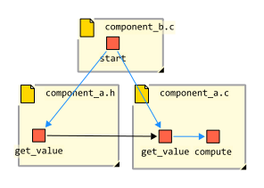
Figure 1: Example for forward declarations in a header file and dependencies.
Declare edges are colored black, Static_Call edges are
colored blue. Only one of the two Static_Call edges will be represented
in the RFG, and its choice is arbitrary.
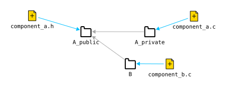
Figure 2: Example architecture with mapping for the example code project. Maps_To
edges are colored blue, Source_Dependency edges are colored gray.
For example, A might represent an interface in a C program, which is represented
in the code by a header file component_a.h, see
Figure 1 above. The header contains declarations of the
routines that should be visible to other code components, like get_value(). There
exists a corresponding source file component_a.c in which the routines declared in
the header are defined, but maybe also other routines that are “private” to the
implementation of component A, like compute(). The routine start() calls
get_value(), but the target of the corresponding call dependency might either point
to the definition or one of the simple declarations of get_value(). This is
illustrated in the figure by the two Static_Call-edges outgoing from
start(): only one of them is contained in the actual Declaration Facts
view, and this choice is arbitrary.
In the architectural model, the header file is mapped to the architecture entity
A_public, the source file is mapped to A_private (see
Figure 2 above). The architectural entity A_private is
not made accessible to other architecture entities. Here the declaration of
get_value() in component_a.h should signal that A_public “offers” the entity
get_value() to other architectural entities like B: the declaration should
allow each architecture entity that has a dependency on component A to also
access get_value(), although its definition is not mapped to A_public.
However, it might be that a declaration d of the entity o is required in a source file for technical reasons, for example a forward declaration of a class which avoids an include statement. If the source file in question is mapped to an architecture entity a, this forward declaration should not imply that architecture entities dependent on a are allowed to access o in most cases. The desired semantics of a declaration with respect to an architecture model can therefore not be expressed in C and C++.
In the following we will describe the means provided by the Axivion Suite to clarify these differing interpretations of declarations more formally. Roughly, the approach works as follows: for each target of an architectural dependency, we compute a set of possible entities in the architecture for the dependency target if the target is a declaration. This set contains
the architecture entity to which the definition of the target code entity is mapped, if existing, and
the architecture entities to which declarations of the code entity are mapped, if they have a (or indirect) “Declaration forwarding”- dependency on the architecture entity corresponding to the definition.
Now it suffices that there is a corresponding dependency in the architecture view
targeting one of the elements in this set to generate convergences. If none of the
elements in the set gives rise to a convergence, a single divergence is reported, with
the original code dependency as causing edge. The architecture target of this divergence
is the architecture entity to which the definition of the code entity is mapped to. The
edge type of “Declaration forwarding”-dependencies is Declare by default,
but can also be specified by the user before an analysis.
4.1.2.3. Modeling using CASE tools and Architecture-As-Code
Besides modeling and mapping the architecture entirely within Gravis, it is also possible to perform an architecture analysis using input from a CASE tool or Architecture-As-Code approaches. The Axivion Suite offers built-in support for models from Sparx Enterprise Architect, IBM Rational Rhapsody, and a subset of models written in the PlantUML format. Other input formats can be supported via custom import scripts. It is also possible to express an architecture using a Python-based description language (“Architecture-As-Code” approach).
Basics
In the following we will illustrate how the architecture check can be implemented based on a CASE tool model. For this we use examples that are intended to serve as a foundation for your own checks. It is important to emphasize that many other modeling styles can be supported by developing matching transformation and mapping rules. You have to clarify your modeling and how your model is related to the source code before you create an architecture analysis, to ensure that the resulting check results are meaningful. The hierarchy and base views can be selected similarly to the manual modeling approach described earlier. For obtaining an architecture view, a mapping view, and a results view, four steps have to be tackled. They are typically performed by using rules already provided by the Axivion Suite or by using rules specifically written for the check in question. The concrete rule configuration depends on the modeling approach and the structure of the source code.
Import the model into the RFG. This step creates a separate view in the RFG, in which the architecture model is contained as RFG nodes and RFG edges. Most of the time these nodes are subtypes of
UML Nodeand edges are subtypes ofUML Dependency. Attributes are used to represent additional information from the model, like names, stereotypes, tagged values, or GUIDs.The structure of the imported model has to be transformed to be useable by the architecture check. Therefore in the second step, the model view is transformed into a new view. This “transformed model view” can serve as basis for an architecture check, more exactly it will be assigned the Architecture role described earlier. In the simplest of cases (see example 1), packages or components are connected by simple edges to express dependencies. Then only the types of the dependency edges have to be interpreted, i.e. transformed into edge types that are subtype of
Source_Dependency, e.g. intoCallrelations if only calls are allowed between entities. If the model uses more sophisticated dependency relations like interface-based connections, a customized rule is used to translate e.g. a dependency modeled using provided and required interfaces into a dependency that can be processed by the architecture verification (see example 2).Create a mapping view that maps nodes from the hierarchy view to the transformed model view. The mapping can be obtained in many different ways. The rule
Architecture-HierarchicalMappingconnects entities having the same or similar names with each other, e.g. directories in code are mapped to packages in the model if their name matches (see example 1). More complex mapping rules are possible. Then special transformations are applied to e.g. connect elements of interfaces to their respective functions, variables or methods (see example 2). It is also possible to provide information about code locations in form of tagged values in the model. Rules likeArchitecture-TaggedValuesMappingcan use them to create a mapping view.Execute the architecture check and obtain convergence, divergence, and absence information.
Example Analyses contained in the Axivion Suite
The rules and configurations described in the examples
can be found in the zip file example/architecture_examples.zip in the installation
of the Axivion Suite, together with a small C source code project called engine_control
and configurations for building and analysing the project using the different modeling
approaches.
More details about running the analyses is given in the README.txt file within the zip file.
Example 1: Package Model (Enterprise Architect)
In the first example, Sparx Enterprise Architect is used as tool to model architectures. The modelling entities are
packages and
edges of type Dependency between packages.
The names of the packages correspond directly to names of directories in the source code project.
A dependency X -> Y represents that all code corresponding to X is allowed to depend on
all code corresponding to Y, e.g., a function belonging to X can call another function in Y,
or access fields of a class belonging to Y etc.
The configuration is located within engine_demo/axivion/package_model
in the zip file example/architecture_examples.zip.
The analysis is performed by using rules already provided by the Axivion Suite:
The model file
package_model.xmiis imported into the RFG by an instance of the ruleArchitecture-EAImporter, generating anEA Architectureview. In the resulting RFG, packages are represented by nodes of typeUML Package, dependency edges are represented by edges of typeUML Dependency. The result of the import can be inspected in Gravis: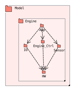
The
UML Dependencyedges in the model are transformed intoSource_Dependencyedges, resulting in theArchitectureview, by an instance of the ruleArchitecture-EdgeInterpretation, visibly by the changed shape and color of the edges: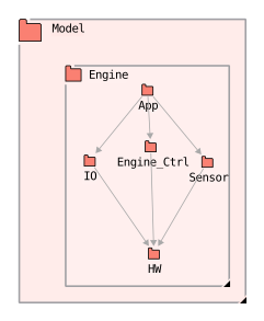
A mapping between
Module(code) andArchitectureis created by an instance of the ruleArchitecture-HierarchicalMapping: directories are mapped to nodes of typeUML Packageby default: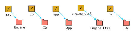
Finally, an instance of the rule
Architecture-ArchitectureCheckperforms the actual architecture check and generates convergences, divergences, and absences, creating a check view: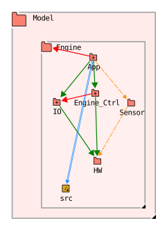
Rules like Architecture-HierarchicalMapping can also issue warnings if e.g. name inconsistencies arise between
code elements and model elements. These findings are processed as stylecheck findings.
Example 2: Port Model (Enterprise Architect)
The second example also uses Sparx Enterprise Architect as CASE tool to model architectures. The meta model is more complex than the previous one, since detailed aspects of communication between software components are used. In particular, dependencies between components are specified using provided and required interfaces.
The modelling entities are
components and packages,
interfaces,
ports,
required and provided interfaces and
edges of type
Dependencybetween provided and required interfaces.
The configuration is located within engine_demo/axivion/package_model in the zip file example/architecture_examples.zip.
Two customized rules are created for this architecture analysis, Architecture-PortModelTransformation
and Architecture-PortModelMapping. Their code can be found in the directory
engine_demo/axivion/port_model/rules.
The analysis is performed by using the following rules:
The model file port_model.xmi is imported into the RFG by an instance of the rule
Architecture-EAImporter, generating anEA Architectureview: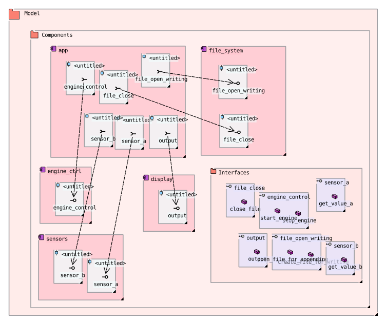
In the resulting RFG, components resp. ports resp. required interface resp. provided interfaces resp. interfaces resp. operations are represented by nodes of type
UML Componentresp.UML Portresp.UML RequiredInterfaceresp.UML ProvidedInterfaceresp.UML Interfaceresp.UML Operation. Interfaces are separately specified in the packageInterfaces: they each contain one or more operations. An interface is implemented by a component; this is represented in the model by a port that contains a provided interface (e.g., theoutputinterface is provided by componentdisplay). It also can be used by another component if the component contains a port with a required interface having the same name as the interface (e.g.outputin componentapp). Components that use the interface operations without such a required interface are violating the model.The
UML Portelements can not directly be checked by the architecture analysis, they have to be transformed. Similarly, the interfaces in this example are not located within their respective components, but separately in a package. Let us look at this detail of the model: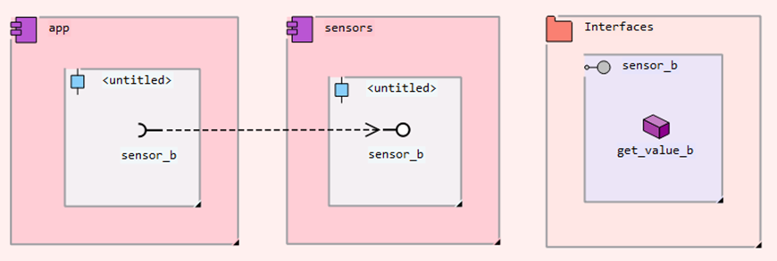
The customized rule
Architecture-PortModelTransformationcopies each interface (e.g.sensor_b) to the component that contains the provided interface for it (forsensor_be.g.sensors), including the contained operations. It then removes ports, provided and required interfaces, and replaces them by edges of typeCall, with source a component requiring an interface I, and target the interface itself, e.g.app->sensor_b: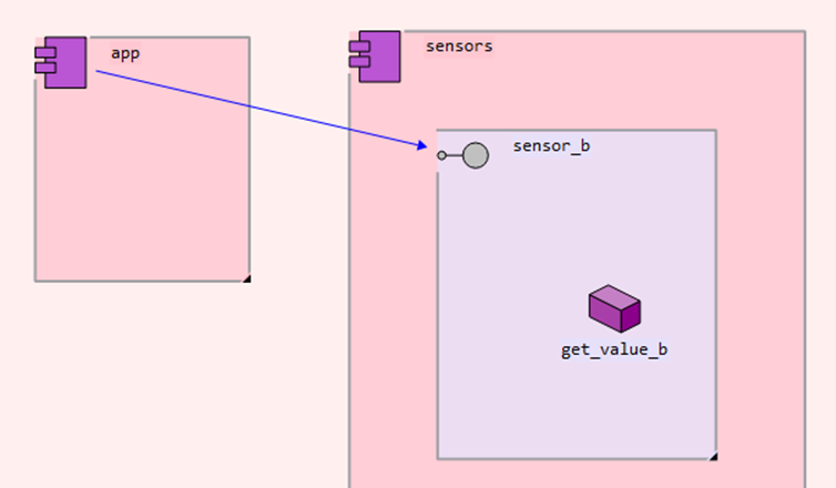
Additionally, since we are only interested in dependencies between components, for each component
Can edgeC->Cof typeSource_Dependencyis added to allow all defined interfaces and other parts of the component to access each other. The result looks like this: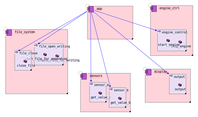
A mapping between
File(code) andArchitectureis created by an instance of the ruleArchitecture-PortModelMapping; by comparing their respective names, directories are mapped to nodes of typeUML Component, functions are mapped to nodes of typeUML Operation: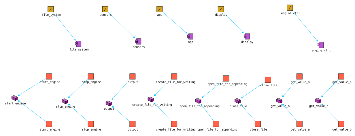
Finally, an instance of the rule
Architecture-ArchitectureCheckperforms the actual check: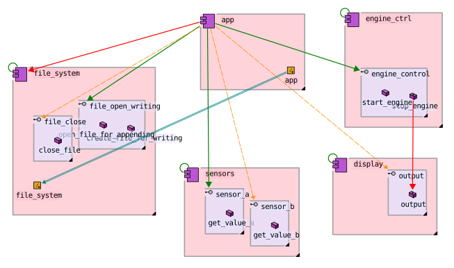
Customized rules like Architecture-PortTransformation can also issue warnings if e.g. the model is
inconsistent (e.g. no interface given for a specified provided interface).
Example 3: Architecture-As-Code
The third example does not use a CASE tool. Instead, architecture model and mapping are both specified using Python files.
The configuration is located within engine_demo/axivion/architecture_as_code
in the zip file example/architecture_examples.zip.
For supporting modelling using Architecture-As-Code, the Axivion Suite provides
the rule Architecture-ScriptedArchitecture and the Python module
bauhaus.architecture.scripted_architecture. This module offers abstractions in form of Python classes
for
architectures,
mappings between architecture and code,
simple components, and
components that are split into a public interface part and a private implementation part.
Architecture and mapping information is specified in one or more several Python files.
In the example project, each top-level component has its own Python file that specifies the
outgoing dependencies of the component as well as information about the mapping from source code to architecture.
Architecture and mapping are specified by the configuration option architecture_files of
rule Architecture-ScriptedArchitecture.
When the rule is executed, it evaluates the files in the given order.
If using more than one Python file for specifying the model, it is advisable to have special
initial and final Python files, in the example model/setup_initial.py and model/setup_final.py, respectively.
In model/initial_setup.py, an Architecture instance ARCH, a Mapping instance MAPPING, and
component instances are created. The global variable INPUT_RFG is made available by
Architecture-ScriptedArchitecture and can be used to access the actual RFG.
# import the basic library for creating architectures and mappings
from bauhaus.architecture.scripted_architecture import *

# Create architecture and mapping abstractions

ARCH = Architecture(
        "My Architecture",
        Component("Engine_Ctrl"),
        Component("Sensor"),
        Component("IO", Component("Display"), Component("File_System")),
        Component("App"),
        ComponentWithInterface("HW"),
    )

MAPPING = Mapping(INPUT_RFG, 'File')

app = ARCH.App # access of components via dot-notation
E.g., a component named Engine_Ctrl is created and given as part of the architecture.
You can also nest components by giving the component additional arguments: for example, component IO contains
two sub-components Display and File_System.
You can access components using dot notation, starting with the architecture, e.g. ARCH.IO.File_System.
You can now define dependencies between components and provide mapping info. Take a look at model/app.py:
app = ARCH.App

# outgoing dependencies
app.depends_on(ARCH.Engine_Ctrl) # app depends on Engine_Ctrl
app.depends_on(ARCH.IO)
app.depends_on(ARCH.Sensor)

# mapping
MAPPING.add_mapping('src/app', app)
The method depends_on allows specifying dependencies. E.g. App depends on Engine_Ctrl.
The mapping can be specified using the method add_mapping of the mapping class. It takes as first argument
a string denoting the path to the desired code node in the used hierarchy view. The names of the nodes in sequence
are separated by slashes. The second argument is the architecture entity (component) to which the node given by the
first argument should be mapped. You can use arbitrary Python syntax to specify a mapping, e.g.:
for suffix in ('final_', 'init_'):
    MAPPING.add_mapping(f'src/{suffix}_app', app)
The component HW is a specialized instance of ComponentWithInterface: these components allow specifying
a private (implementation) part and a public part. If another component is allowed to access
HW, it is only allowed to access this public part. You can use the is_private argument
of the add_mapping method to specify whether a code entity should be mapped to the private or public part, see
model/hw.py:
hw = ARCH.HW

# mapping
# everything in the component is private...
MAPPING.add_mapping('src/hw', hw, is_private=True)
# except public headers (like hw_public.h)
MAPPING.add_mapping('src/hw/hw_public.h', hw, is_private=False)
MAPPING.add_mapping('src/hw/error_code.h', hw, is_private=False)
After specifying the architecture in this way, model/setup_final.py creates the resulting architecture
and mapping views in the RFG:
# At the end: create the actual views.
ARCH.create_view(INPUT_RFG, "Architecture")
MAPPING.create_mapping_view("Mapping")
The analysis is performed by using the following rules:
The execution of
Architecture-ScriptedArchitecturecreates the viewsArchitectureandMapping.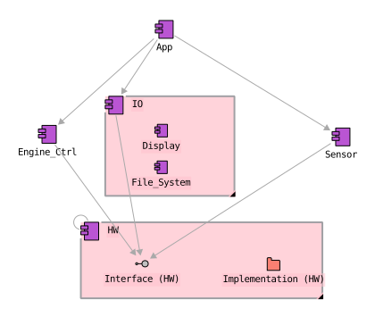
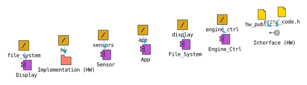
An instance of the rule
Architecture-ArchitectureCheckperforms the actual architecture check: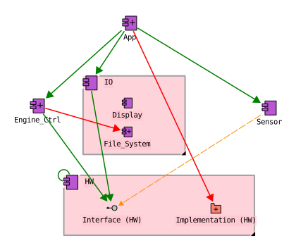
4.1.2.4. Architecture Reengineering
In addition to checking the conformance of the source code to an architecture, it is also possible to use the Axivion Suite for reengineering an architecture from the source code from scratch.
This can be useful if the architecture model is outdated and does not reflect the current state of the software system, or if there is no architecture model at all and one needs to be created based on the source code. In particular for modelling the detailed design of a system down to routine and variable level, it can be very time-consuming to create an architecture model manually. Therefore it is often more efficient to reengineer the architecture from the source code and then refine it manually.
The reengineering functionality provided by the Axivion Suite offers multiple configuration options to control the resulting architecture model, e.g. to specify which source code dependencies should be considered for the reengineering and how they should be interpreted, or to specify how the resulting architecture model should look like (e.g. whether it should contain only components or also details like structs, classes and routines / operations, and how they should be modelled).
The resulting generated architecture model represents the current state of the software system, including all current dependencies. It can then be used as a startingpoint for architecture modelling and is ready for use in architecture verification. It is also possible to export this reengineered architecture model to Enterprise Architect, using one of two exporter rules provided by the Axivion Suite, and use this tool as base for architecture verification.
We will in the following illustrate how to reengineer an architecture from scratch for a C-based project. We will then show how the workflow of using the resulting architecture model for architecture verification looks like. There are two options for that:
Use Gravis as base for architecture verification.
Export the resulting architecture model to Enterprise Architect (EA) so that EA can be used for modelling or just representing the architecture.
We will list some additional information about modelling more architectural details in the end of this section.
Example Analyses contained in the Axivion Suite
Similarly to the examples in Modeling using CASE tools and Architecture-As-Code,
rules and configurations described in the following
can be found in the zip file example/architecture_examples.zip in the installation
of the Axivion Suite, together with example source code.
More details about running the “base” analysis is given in the README.txt file
within the zip file. The corresponding configuration directory is reengineering.
Reengineering an architecture from scratch for a C-based project
We create an architecture from scratch for the example project engine_control.
We have to clarify how our architecture should look like and what should be represented. We start by putting together the following modelling rules:
Directories should be modelled as packages in the architecture.
Source code modules (i.e. compilation units) should be modelled as components in the architecture.
Dependencies should be modelled as edges between the components.
These modelling decisions are reflected by the choice of configuration options for rule Architecture-Reengineering in the different configurations.
Note that the example uses the RFG hierarchy view Module, in which a header
file and its corresponding implementation file are already represented by a
single Module node, so e.g. engine.c and engine.h yield one component
engine. With the hierarchy view File (the default of rule
Architecture-Reengineering), header and implementation files are represented
as separate components that share their name but are distinguished by their
linkage names.
The modelling is somewhat similar to the “Package model” in Modeling using CASE tools and Architecture-As-Code. However, files are now modelled as components, and dependencies are modelled on component level, not on package level. The resulting architecture model is shown in the figure below - first the model in Gravis, then the same model in EA after export.
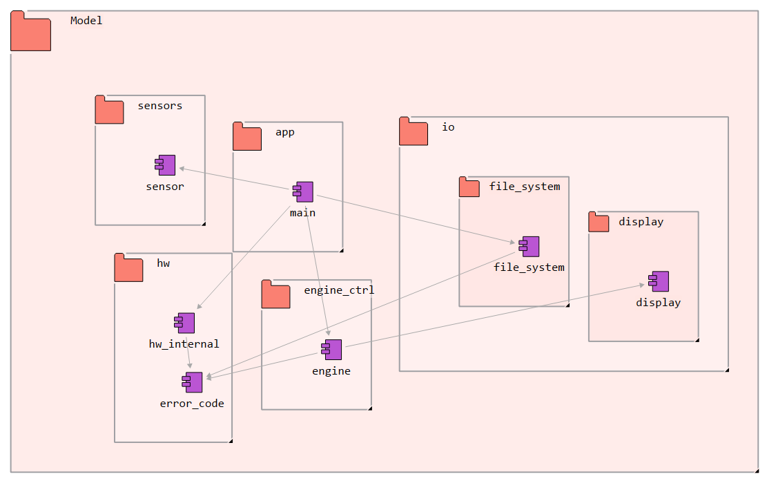
Reengineered architecture in Gravis.
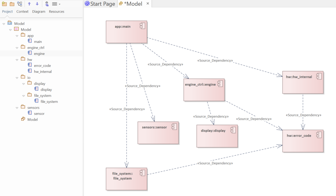
Reengineered architecture in Enterprise Architect. Diagram has been created manually.
There are many variations possible for the modelling rules and the resulting architecture model.
We now explain in detail two different workflows for architecture reengineering;
see also the WORKFLOW.txt file in directory reengineering in the zip file
example/architecture_examples.zip for more details about running the different workflows.
Workflow 1: Export to GXL and verify in Gravis
In this workflow, the reengineered architecture is exported to GXL files that can then be used directly in Gravis for architecture verification.
Initial Reengineering: Extract the architecture from code and export to GXL:
do_reengineering.bat gravis
This uses
reengineering_config_gravis.jsonand exports the architecture and mapping toarchitecture.gxlandmapping.gxl. It generates an architecture by instantiating the rule Architecture-Reengineering with configuration options that reflect the modelling decisions described above. This step is normally only done once to obtain the initial architecture and mapping. You can then modify these GXL files if you want to refine the architecture model or the mapping.Verification: Verify using the exported GXL files:
gravis_based_analysis.bat
This uses
gravis_based_analysis.jsonto import the GXL files and run architecture verification (see Architecture Analysis). This is the mode that is intended to be used for “day-to-day” architecture verification using Gravis.
Workflow 2: Export to Enterprise Architect and verify
In the alternative workflow, the reengineered architecture is exported to an Enterprise
Architect file (model.qea) where it can be inspected and refined before being
used for architecture verification.
Initial Reengineering: Extract the architecture from code and export to EA:
do_reengineering.bat ea
or
do_reengineering.bat ea_native
This uses
reengineering_config_ea.jsonto extract the architecture and export it intomodel.qea. Theeavariant uses an interface to an existing Enterprise Architect installation to generate themodel.qea, while theea_nativevariant does not require an existing Enterprise Architect installation. Hence, if you are planning to use a system other than Windows or which cannot provide an Enterprise Architect installation, you should use theea_nativevariant. The rule used by theeavariant isArchitecture-EAExporterCom, while theea_nativevariant uses the ruleArchitecture-QEAExporter. Theeaand theea_nativevariants do not generate necessarily the exact same results.Note that any previous content of
model.qeais overwritten in this step.Verification: Verify the code against the exported architecture:
ea_based_analysis.bat
This uses
ea_based_analysis.jsonto import the architecture frommodel.qeaand run architecture verification. The configuration again instantiates the rule Architecture-Reengineering, but uses a slightly different “mode” for the rule: the option external_architecture_view_name is now set to “EA Architecture” (the imported EA view name). In this mode, the rule creates again an architecture by inspecting the actual source code, but then also compares it to the external architecture view, and reports structural differences between the current state of the source code and the imported architecture as stylecheck findings. This can happen e.g. if new components have not been added correctly to the initial model in the course of the project evolution. The external architecture view is not “overwritten” by the current state. When comparing the generated architecture with the external architecture view, elements are matched by name and type. If several sibling elements share name and type (e.g. separate components for header and implementation files when using theFilehierarchy view, or overloaded operations in the detailed modeling), they are matched via the tagged valueAxivion.LinkageName, which the EA exporters attach to every generated element by default and the EA importers import by default (see option imported_tagged_values of rule Architecture-QEAImporter). The tagged value can be edited within Enterprise Architect, e.g. to resolve ambiguities for elements that were added to the model manually. To find the linkage name of an element when remodeling, look it up on the corresponding element of the generated architecture: Gravis shows it as theLinkage.Nameattribute of the element, and a freshly exported EA model carries it in theAxivion.LinkageNametagged value. The rule generates two additional views:“EA Architecture Mapping”: a mapping view between the current state and the external architecture view.
“EA Architecture for check”: an actual architecture view structurally similar to the external architecture view, but in which the edge types are translated from UML-based dependencies to source dependencies.
These two views are then used for the actual architecture check.
With this approach, the architect is able to model within EA and use the Architecture Verification feature of the Axivion Suite. For this she has to obey the modelling rules defined for Architecture-Reengineering to ensure that the resulting architecture can be used for architecture verification (e.g. in our example: modelling directories as packages etc.). In later versions of the Axivion Suite, we plan to provide more flexibility for modelling within EA, e.g. by allowing to have an additional logical layer above the reengineered architecture, in which the architect can model more freely.
Options for modelling more architectural details
The model in the example keeps things simple, in that it only models directories and source modules. The rule Architecture-Reengineering however offers many options for modelling more details in the architecture, e.g. to reengineer the detailed design level of the software project: Types like classes, structs and unions, routines and methods and also variables can be reengineered as well. The example contains therefore a variant of (2) that uses a more refined architecture model:
do_reengineering.bat ea_detailedor
do_reengineering.bat ea_detailed_nativeea_based_detailed_analysis.bat
It also considers classes, structs, unions, routines, methods (for C++), variables and typedefs as architecture entities. The translation can be controlled by the option transformation of the rule Architecture-Reengineering (see reengineering_config_ea_detailed.json):
RFG node types like Class, Routine, Method, Constant, Member, and Variable are translated into UML-based architecture entities, using the config option transformation.node_translation
Dependencies are possible between Class and Component entities, as specified by the option transformation.node_types_with_dependencies
Instead of just generating edges of type Source_Dependency, the option transformation.detailed_dependencies allows to translate different RFG edge types.
In addition, the number of calls between two entities is also annotated on edges, by setting the option transformation.annotate_dependency_counts to the edge type to be counted (
Callin the example).
The resulting architecture in EA is shown in the figure below.
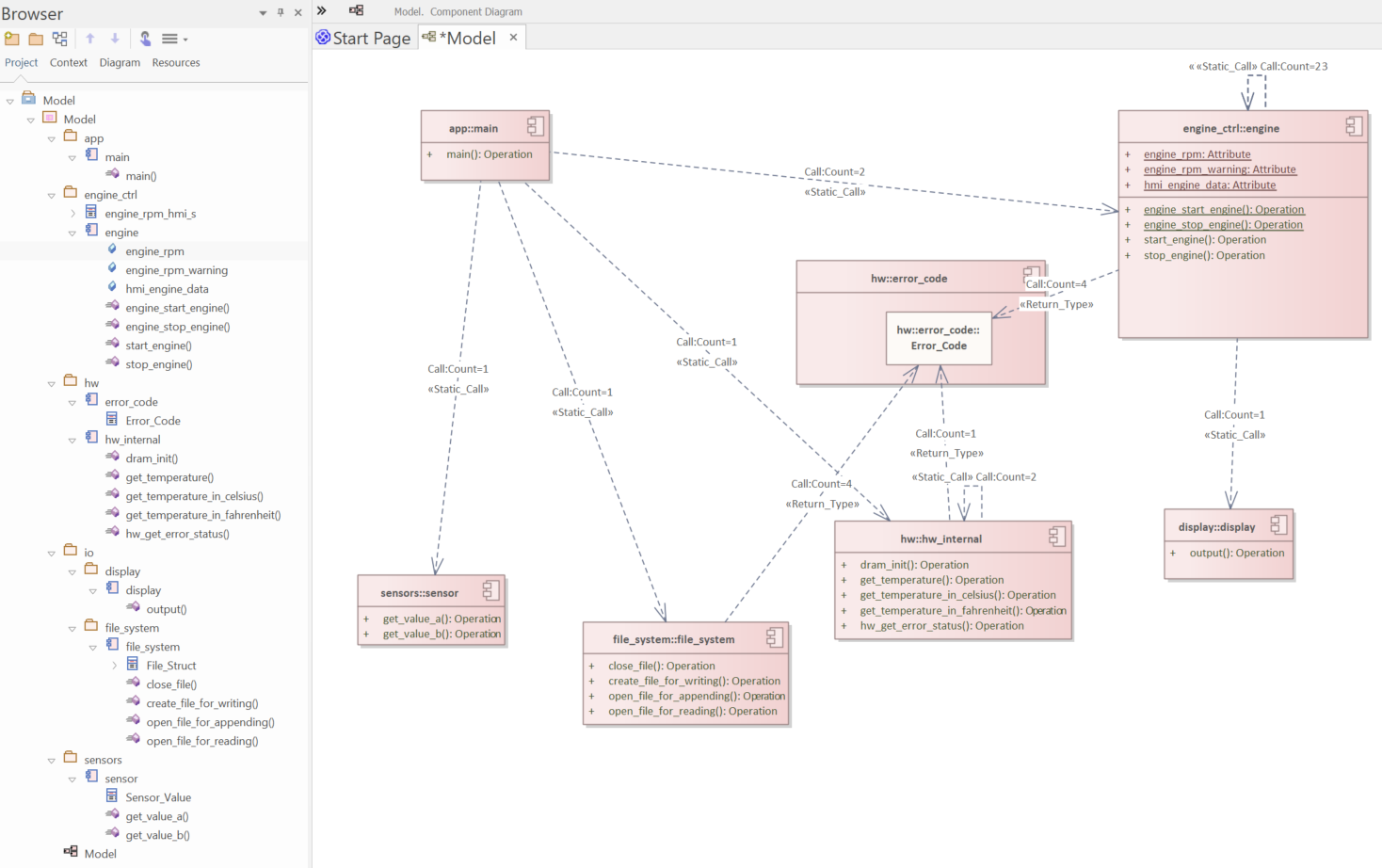
Reengineered detailed architecture in Enterprise Architect. Diagram has been created manually.
4.1.2.5. Qt signal-slot connections
Signal-slot connections are an essential aspect of software systems that are based on the Qt Framework. The Frameworks-QtSupport rule can add Qt-specific edges to the graph that represent these connections in the RFG. If the rule is enabled its create_qt_connect_edges option (enabled by default) controls whether these edges are created.
Consider a class SpeedSensor with a signal value_changed(int) and a class
SpeedIndicator with a slot update(int). A third class InstrumentPanel has a method
setup_components() in which the signal SpeedSensor::value_changed is connected to the
slot SpeedIndicator::update.
In the Code Facts view, this will add the following edges:
A
Qt_Connect_Signaledge fromsetup_componentsto theSpeedSensor::value_changedsignal. Please note that this signal node belongs to the generated moc file for the header file defining SpeedSensor because that is where its generated implementation is found.A
Qt_Connect_Slotedge fromsetup_componentsto theSpeedIndicator::updateslot. This slot node belongs to the regular source file in which the method is implemented.A
Qt_MetaObject_Calledge from the signal to the slot that represents the dynamic call that is made at run-time.
Figure 3 shows the resulting RFG structure.
Note
The source location of the node representing the signal and that of the Qt_MetaObject_Call edge
representing the dynamic call are both in the generated moc file. That means that any violations that
would be reported for these entities are excluded because the Frameworks-QtSupport rule adds a global exclude
pattern for the generated moc files.
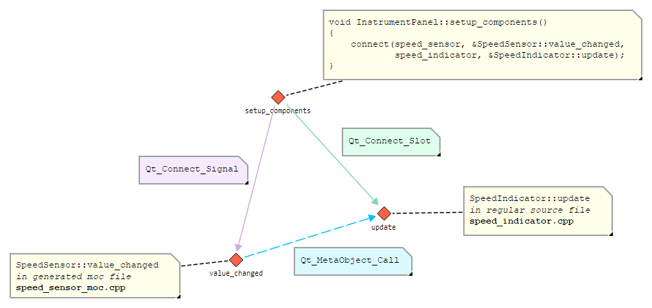
Figure 3: Edges representing signal-slot connections
The structure in Declaration Facts looks similar, except that the method node for setup_components
belongs to the header file in which the class InstrumentPanel is declared and the method node for
SpeedIndicator::update belongs to the header file in which the class SpeedIndicator is declared. The
node for the SpeedSensor::value_changed signal still belongs to the generated moc file as in the
Code Facts view.
Note
The Qt_Connect_Signal and Qt_Connect_Slot edges are particularly important if the old
connect() mechanism using the SIGNAL and SLOT macros is used because the signal and slot
functions would be considered dead code without these edges. If the newer mechanism using member function pointers is
used, then there are already Method_Address edges between the routines containing the connect()
calls and the referenced signal/slot member functions.
4.1.3. FAQ
Q: How do I configure Gravis architecture checks using exported GXL files?
A: Follow these steps to configure Gravis architecture checks using exported GXL files:
Open the project configuration with
axivion_configSelect the configuration layer where you want architecture checks
Search for
Architecture-GravisArchitecturerule and enable itConfigure the
architecture_fileandmapping_fileoptions by double-clicking them and selecting your exported GXL filesSave the configuration and run your analysis with your usual method (e.g.,
start_analysis.bat)