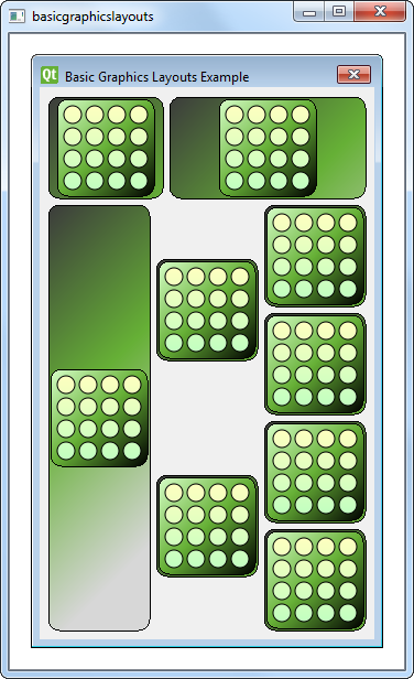
기본 그래픽 레이아웃 예시
기본 그래픽 레이아웃을 만드는 방법을 보여줍니다.
기본 그래픽 레이아웃 예제에서는 QGraphicsView: QGraphicsLinearLayout 및 QGraphicsGridLayout 의 레이아웃 클래스를 사용하는 방법을 보여 줍니다. 또한 사용자 지정 레이아웃 항목을 작성하는 방법도 보여줍니다.

창 클래스 정의
Window 클래스는 QGraphicsWidget 의 하위 클래스이며 QGraphicsWidget parent 을 매개변수로 하는 생성자가 있습니다.
class Window : public QGraphicsWidget
{
    Q_OBJECT
public:
    Window(QGraphicsWidget *parent = nullptr);

};
창 클래스 구현
Window 의 생성자는 QGraphicsLinearLayout 객체 windowLayout 를 세로 방향으로 인스턴스화합니다. 부모가 windowLayout 인 또 다른 QGraphicsLinearLayout 객체 linear 를 인스턴스화합니다. 다음으로 LayoutItem 객체 item 를 생성하고 addItem() 함수를 사용하여 linear 에 추가합니다. 또한 item 에 stretchFactor 을 제공합니다.
    QGraphicsLinearLayout *windowLayout = new QGraphicsLinearLayout(Qt::Vertical);
    QGraphicsLinearLayout *linear = new QGraphicsLinearLayout(windowLayout);
    LayoutItem *item = new LayoutItem;
    linear->addItem(item);
    linear->setStretchFactor(item, 1);
이 과정을 반복합니다:
LayoutItem을 새로 만듭니다,linear항목을 추가하고- 스트레치 인자를 제공합니다.
    item = new LayoutItem;
    linear->addItem(item);
    linear->setStretchFactor(item, 3);
    windowLayout->addItem(linear);
그런 다음 windowLayout 에 linear 를 추가하고 QGraphicsLinearLayout 객체 두 개를 중첩합니다. QGraphicsLinearLayout 객체 외에도 QGraphicsGridLayout 객체, grid 객체를 사용하는데, 이는 4x3 그리드이며 일부 셀이 다른 행에 걸쳐 있습니다.
아래 코드 스니펫에 표시된 것처럼 addItem() 함수를 사용하여 LayoutItem 객체를 7개 생성하고 grid 에 배치합니다:
    QGraphicsGridLayout *grid = new QGraphicsGridLayout(windowLayout);
    item = new LayoutItem;
    grid->addItem(item, 0, 0, 4, 1);
    item = new LayoutItem;
    item->setMaximumHeight(item->minimumHeight());
    grid->addItem(item, 0, 1, 2, 1, Qt::AlignVCenter);
    item = new LayoutItem;
    item->setMaximumHeight(item->minimumHeight());
    grid->addItem(item, 2, 1, 2, 1, Qt::AlignVCenter);
    item = new LayoutItem;
    grid->addItem(item, 0, 2);
    item = new LayoutItem;
    grid->addItem(item, 1, 2);
    item = new LayoutItem;
    grid->addItem(item, 2, 2);
    item = new LayoutItem;
    grid->addItem(item, 3, 2);
    windowLayout->addItem(grid);
grid 에 추가하는 첫 번째 항목은 네 행에 걸쳐 왼쪽 상단 셀에 배치됩니다. 다음 두 항목은 두 번째 열에 배치되며 두 행에 걸쳐 있습니다. 각 항목의 maximumHeight() 및 minimumHeight()은 세로로 확장되지 않도록 동일하게 설정됩니다. 결과적으로 이러한 항목은 해당 셀에 세로로 맞지 않습니다. 따라서 Qt::AlignVCenter 을 사용하여 셀의 중앙에 세로로 정렬되도록 지정합니다.
마지막으로 grid 자체가 windowLayout 에 추가됩니다. QGridLayout::addItem()와 달리 QGraphicsGridLayout::addItem()는 인자로 행과 열을 지정하여 항목이 어느 셀에 위치할지 지정해야 합니다. 또한 rowSpan 및 columnSpan 인수를 생략하면 기본값은 1이 됩니다.
모든 항목이 windowLayout 에 추가되므로 구성하는 각 LayoutItem 에 대해 부모를 지정하지 않습니다. 레이아웃에 항목을 추가하면 레이아웃이 설치된 위젯에 자동으로 부모가 다시 지정됩니다.
    setLayout(windowLayout);
    setWindowTitle(tr("Basic Graphics Layouts Example"));
이제 grid 을 설정하고 windowLayout 에 추가했으므로 QGraphicsWidget::setLayout()을 사용하여 windowLayout 을 창 객체에 설치하고 창 제목을 설정합니다.
레이아웃 항목 클래스 정의
LayoutItem 클래스는 QGraphicsLayoutItem 및 QGraphicsItem 의 서브 클래스입니다. 생성자, 소멸자 및 몇 가지 필수 재구현이 있습니다. QGraphicsLayoutItem 을 상속하므로 {QGraphicsLayoutItem::setGeometry()}{setGeometry()} 및 {QGraphicsLayoutItem::sizeHint()}{sizeHint()}를 다시 구현해야 합니다. 또한 QGraphicsItem 을 상속하므로 {QGraphicsItem::boundingRect()}{boundingRect()} 및 {QGraphicsItem::paint()}{paint()}를 다시 구현해야 합니다.
class LayoutItem : public QGraphicsLayoutItem, public QGraphicsItem
{
public:
    LayoutItem(QGraphicsItem *parent = nullptr);

    // Inherited from QGraphicsLayoutItem
    void setGeometry(const QRectF &geom) override;
    QSizeF sizeHint(Qt::SizeHint which, const QSizeF &constraint = QSizeF()) const override;

    // Inherited from QGraphicsItem
    QRectF boundingRect() const override;
    void paint(QPainter *painter, const QStyleOptionGraphicsItem *option, QWidget *widget = nullptr) override;

private:
    QPixmap m_pix;
};
LayoutItem 클래스에는 QPixmap, m_pix 의 비공개 인스턴스도 있습니다.
LayoutItem 클래스 구현
LayoutItem 의 생성자에서 m_pix 이 인스턴스화되고 block.png 이미지가 로드됩니다.
LayoutItem::LayoutItem(QGraphicsItem *parent)
    : QGraphicsLayoutItem(), QGraphicsItem(parent),
      m_pix(QPixmap(QLatin1String(":/images/block.png")))
{
    setGraphicsItem(this);
}
Q_UNUSED() 매크로를 사용하여 컴파일러가 사용하지 않은 매개변수에 대한 경고를 생성하지 않도록 합니다.
void LayoutItem::paint(QPainter *painter, const QStyleOptionGraphicsItem *option,
                       QWidget *widget)
{
    Q_UNUSED(widget);
    Q_UNUSED(option);

    QRectF frame(QPointF(0, 0), geometry().size());
    const QSize pmSize = m_pix.size();
    QGradientStops stops;
paint() 함수의 기본 개념은 배경 직사각형을 그린 다음 픽셀맵 주위에 직사각형을 그리는 것입니다.
    // paint a background rect (with gradient)
    QLinearGradient gradient(frame.topLeft(), frame.topLeft() + QPointF(200,200));
    stops << QGradientStop(0.0, QColor(60, 60,  60));
    stops << QGradientStop(frame.height() / 2 / frame.height(), QColor(102, 176, 54));

    //stops << QGradientStop(((frame.height() + h)/2 )/frame.height(), QColor(157, 195,  55));
    stops << QGradientStop(1.0, QColor(215, 215, 215));
    gradient.setStops(stops);
    painter->setBrush(QBrush(gradient));
    painter->drawRoundedRect(frame, 10.0, 10.0);

    // paint a rect around the pixmap (with gradient)
    QPointF pixpos = frame.center() - (QPointF(pmSize.width(), pmSize.height()) / 2);
    QRectF innerFrame(pixpos, pmSize);
    innerFrame.adjust(-4, -4, 4, 4);
    gradient.setStart(innerFrame.topLeft());
    gradient.setFinalStop(innerFrame.bottomRight());
    stops.clear();
    stops << QGradientStop(0.0, QColor(215, 255, 200));
    stops << QGradientStop(0.5, QColor(102, 176, 54));
    stops << QGradientStop(1.0, QColor(0, 0,  0));
    gradient.setStops(stops);
    painter->setBrush(QBrush(gradient));
    painter->drawRoundedRect(innerFrame, 10.0, 10.0);
    painter->drawPixmap(pixpos, m_pix);
}
boundingRect()를 다시 구현하면 왼쪽 상단 모서리가 (0,0)으로 설정되고 그 크기는 레이아웃 항목 geometry()의 크기가 됩니다. 이 영역이 우리가 칠하는 영역입니다.
setGeometry()의 재구현은 단순히 베이스클래스 구현을 호출합니다. 그러나 이렇게 하면 boundingRect가 변경되므로 prepareGeometryChange()도 호출해야 합니다. 마지막으로 geom.topLeft() 에 따라 항목을 이동합니다.
void LayoutItem::setGeometry(const QRectF &geom)
{
    prepareGeometryChange();
    QGraphicsLayoutItem::setGeometry(geom);
    setPos(geom.topLeft());
}
항목의 크기가 픽셀맵보다 작아지는 것을 원하지 않으므로 m_pix 보다 큰 크기 힌트를 반환해야 합니다. 또한 나중에 칠할 테두리를 위해 주변에 여분의 공간을 추가합니다. 또는 항목이 픽셀맵보다 작아지지 않도록 픽셀맵의 크기를 조정할 수 있습니다. 기본 크기는 최소 크기 힌트와 동일하며, 최대 크기는 큰 값으로 설정합니다.
QSizeF LayoutItem::sizeHint(Qt::SizeHint which, const QSizeF &constraint) const
{
    switch (which) {
    case Qt::MinimumSize:
    case Qt::PreferredSize:
        // Do not allow a size smaller than the pixmap with two frames around it.
        return m_pix.size() + QSize(12, 12);
    case Qt::MaximumSize:
        return QSizeF(1000,1000);
    default:
        break;
    }
    return constraint;
}
© 2025 The Qt Company Ltd. Documentation contributions included herein are the copyrights of their respective owners. The documentation provided herein is licensed under the terms of the GNU Free Documentation License version 1.3 as published by the Free Software Foundation. Qt and respective logos are trademarks of The Qt Company Ltd. in Finland and/or other countries worldwide. All other trademarks are property of their respective owners.

