C
Studio: Inspector Palette
The Inspector palette is the most-used palette in Studio. It is used to control which properties are animated or change on a per-slide basis and the values for each of those properties.
Animating Properties
Almost every property of every element may be animated at runtime. Non-animatable exceptions are properties with discrete values (booleans, text strings, or drop-down lists).
Properties that can be animated have a small stopwatch icon next to them in the Inspector palette. Click on this icon to enable animation for an property.
Turning off the toggle for an property with complex animation saves the keyframes during the same session; if you accidentally turn off animation you can turn it back on and all your keyframes will come back. However, if you save your presentation with the animation turned off, those keyframes are discarded. Re-enabling animation after re-opening the presentation will start with a blank slate.
Unlinking from the Master Slide
By default, elements on the master slide have the same property values on all slides. If you change the scale of an object that change is applied on all slides. However, it is also possible to unlink any property of a master element. An unlinked property can have custom values and animations for each slide.
To unlink a property, right-click on the property name in the inspector palette and choose Unlink Property from Master Slide. The name of the property will change from green to light grey. This is the same color used for the name of elements that are present only on a single slide, and the properties of such elements.
Tip: When you first unlink a property, the current value for that property (including any animation keyframes) is used as the value for every slide. If you want a similar but slightly different animation on all or most slides, first create the animation on the master slide and then unlink the property and tweak the animation on other slides.
Editing Numeric Values
Studio provides two mechanisms for experimentally changing numeric values in the Inspector palette when you are not sure of the exact value you want.
- When a numeric input is not already focused (ready to be typed into), click and drag the mouse up and down on the number you want to change. The value will increase or decrease as you drag the mouse, and the scene view will update to show the effect of the change.
- With a numeric input focused, press the up/down arrow keys to increment/decrement the value by 1 for each key press.
With both of these techniques, you can hold down the shift key to make the values adjust by 10 instead of 1, or hold down the control key to make the values adjust by 0.1 instead.
Scene/Component Properties
Scenes and components are both "time contexts". When their contents are displayed in the Timeline palette (when you are "inside" the scene or component) and the element is selected, the following properties are shown in the Inspector palette specific to the active slide:
- Play Mode: Controls what happens when the playhead reaches the end time for the slide:
Stop at end- This default value simply holds the playhead at the end time, with any animated properties holding their final value.Looping- Upon reaching the final time the playhead starts over at time 0.PingPong- Upon reaching the final time the playhead starts playing backwards; upon reaching time 0 the playhead starts playing forwards again.Ping- Similar to PingPong, but when the playhead reaches time 0 it stops playback and holds that time.Play Through To...- Upon reaching the final time the scene or component will switch to a new slide. This is useful to have an intro animation that then leads into a looping animation (on a separate slide). You may specify a specific slide to play through to, or simply the next/previous slide in the Slide palette.
- Initial Play State - When entering this slide, should the playhead immediately start playing, or wait to be started? Using the Pause setting is particularly useful when QML application is going to control the time for the context and you don't need or want the runtime attempting to do its own work.
- Use Background - Clear the contents to a solid color before each frame.
- Background Color - Color to use for the background.
Layer Properties
Selecting a layer in the Timeline palette shows the following properties in the Inspector palette:
- Layer Background - Controls how the layer clears when it starts to render each frame:
Transparent- Clear the layer to transparent each frame so that content behind it can be seen.Solid Color- Clear this layer to a non-transparent color. This provides a slight performance boost if the layer fills the viewport and if you turn off "Enable Background Color" for the Scene.Unspecified- Do not clear layer each frame. This provides a slight performance boost if the layer is filled with content, and hence will fully overwrite the previous result.
- Blend Mode - Controls how colors in the active layer blends with colors in the background layer. For details see the discussion on the Blend Mode page.
Normal- Default blend mode. Opaque objects will occlude objects in layers behind.Screen- Colors are blended using an inverted multiply, producing a lighter result.Multiply- Colors are blended using a multiply, producing a darker result.Add- Colors are blended by addition, producing a lighter result.Subtract- Colors are blended by subtraction, producing a darker result.Overlay- A mix ofMultiplyandScreenmodes, producing a result with higher contrast.Colorburn- Colors are blended by inverted division where the result also is inverted, producing a darker result. Darker thanMultiply.Colordodge- Colors are blended by inverted division, producing a lighter result. Lighter thanScreen.
- Sub-Presentation - Select a presentation (.uip) or QML (
.qml) file to render as a sub-presentation on this layer. Other objects on the layer will not render when a sub-presentation is applied. For more information, see Using Sub-Presentations. - Progressive AA - Controls whether progressive anti-aliasing is used when rendering the layer. For details see the discussion on Progressive Anti-Aliasing.
- Multisample AA - Controls whether multisample anti-aliasing is used when rendering the layer. For details see the discussion on Multisample Anti-Aliasing.
- Temporal AA - Controls whether temporal anti-aliasing is used when rendering the layer. For details see the discussion on Temporal Anti-Aliasing.
- Horizontal Fields - Choose which two fields of
Left,Width, andRightare used to control the horizontal placement and sizing of the layer within the presentation. - Left - The distance between the left edges of the presentation and the layer, either in pixels or as a percentage of the presentation's width.
- Width - The width of the layer, either in pixels or as a percentage of the presentation's width.
- Right - The distance between the right edges of the presentation and the layer, either in pixels or as a percentage of the presentation's width.
- Vertical Fields - Choose which two fields of
Top,Height, andBottomare used to control the vertical placement and sizing of the layer within the presentation. - Top - The distance between the top edges of the presentation and the layer, either in pixels or as a percentage of the presentation's height.
- Height - The height of the layer, either in pixels or as a percentage of the presentation's height.
- Bottom - The distance between the bottom edges of the presentation and the layer, either in pixels or as a percentage of the presentation's height.
- Dynamic Resize - The layer is resized dynamically based on the content. This allows the layer texture to be the smallest possible in order to increase performance. The texture is continuously resized as the content changes.
- Padding - The resized layer can be padded. This lowers the amount of resizes needed as the content changes. The layer is resized only when the content changes so much that it exceeds the previous padded size. Padding is also used in reverse to calculate the lower bounds. When the content changes to be smaller, the resize only happens after it takes less space than the lower bounds. The padding can be expressed in pixels or as percentage of the layer size.
- Combine Bounds - When
Dynamic Resizeis in use, the bounds of the objects inside the layer have to be calculated. When this property is disabled, all object bounds are calculated separately and a more accurate layer resize is done based on those separated bounds. When this property is enabled, the object bound calculations are combined, causing more inaccurate but faster results. - Ambient Occlusion - Enables ambient occlusion (AO). AO is a form of approximated global illumination which causes non-directional self-shadowing where objects are close together. Disabling ambient occlusion improves performance at a cost to the visual realism of 3D objects rendered in the layer.
- AO Strength - Controls the strength of the ambient occlusion. A value of
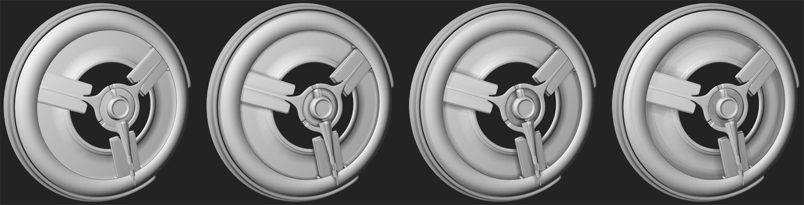
100causes full darkness shadows; lower values cause the shadowing to appear lighter. A value of0effectively disables ambient occlusion. All values other than0have the same impact to the performance, when Ambient Occlusion is toggled on. - AO Distance - Roughly how far (in world units) ambient occlusion shadows spread away from objects. The following graphic illustrates a variety of distances, starting with 0 (no AO) at left. Greater distances cause increasing impact to performance.
- AO Softness - How smooth the edges of the AO shading are. The following graphic illustrates a variety of softness values, going from
0at left to100at right.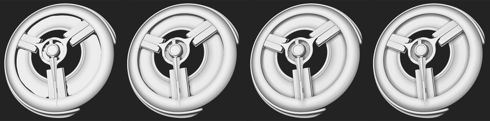
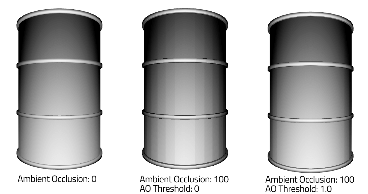
- AO Threshold - A cutoff distance preventing objects from exhibiting AO at close distances. Higher values increase the distance required between objects before AO is seen.
Note: If you see AO shadowing on objects where there should be no shadowing, increase the AO Threshold value slightly to clip away close results.
Note: On objects with smooth shading, it is possible that AO makes the faces of an object appear since AO occurs on the original mesh without smooth shading applied. To avoid this, adjusting the AO Threshold value might help. Usually a value between 0.1 and 1.0 will give a good result.
- AO Sampling Rate - Larger values result in better AO quality (more shades of gray) at the expense of performance.
- AO Detail - Scatters the edges of the AO shadow bands to improve smoothness (at the risk of sometimes producing obvious patterned artifacts).
Note: Very large distances between the clipping planes of your camera may cause problems with AO. If you are seeing odd banding in your AO, try adjusting the Far Clip Plane of your camera to be closer to your content.
- Light Probe - Select an image (preferably a high dynamic range image (
.hdr)) to use to light the scene, either instead of or in addition to standard lights. If selected, note that this image will be used as the environment for any custom.shader, instead of the environment often associated with them. For details see Using Image-based Lighting. - IBL Brightness - The amount of light emitted by the light probe.
- IBL Horizon Cutoff - Increasing the value will add darkness (black) to the bottom half of the environment, forcing the lighting to come predominantly from the top of the image (and removing specific reflections from the lower half).
- IBL FOV Angle - The image source field of view.
- Secondary Light Probe - Select an image to use as secondary IBL light source.
- Probe Crossfade - The blend amount between the primary and secondary light probes.
- Disable Depth Test - Controls whether depth-testing is used when rendering objects in the layer. For details see the discussion on the Disable Depth Test page.
- Disable Depth Prepass - Controls whether depth prepassing is used when rendering objects in the layer. Can be enabled to optimize render speed on layers with low depth complexity.
Transform Properties
Selecting an element in the Timeline palette that has a 3D presence shows the following properties in the Inspector palette:
- Position - The local position of the element in the space established by the parent element. Note that Qt 3D Studio uses a Y-up "left-handed" coordinate system. Increasing values of X go to the right (as seen from the default camera location), increasing values of Y go up, and increasing values of Z go away from the camera.
- Rotation - The local rotation of the element in the space established by the parent element. Each value is the left-handed rotation about the axis in question, with the direction of the axes as described above. Rotations are applied in the order ZXY.
- Scale - The local scale of the element in the space established by the parent element. Note that an odd-number of negative scale values will cause your element to render 'inside-out', which cannot be seen due to backface-culling.
- Pivot - The local pivot offset for the object. You can think of the pivot as offsetting the geometry for the element away from the origin, allowing an object to rotate and scale around a point other than its local origin. Pivots are applied before scaling and rotation.
- Opacity - Although not technically a transformation, every transformable element has an opacity applied to it. An opacity of 100 causes the object to be fully opaque, while an opacity of 0 prevents an object from rendering at all.
Just as modifying the position or rotation of a parent element affects all descendant elements, opacity is multiplicatively cumulative through the transform hierarchy. A cube that is 50% opaque inside a group that is 80% opaque will render with an equivalent apperance of 40% opacity (0.8 * 0.5 = 0.4). Setting the opacity of a group to 0 will prevent any descendants within the group from rendering.
For models, having an equivalent opacity of 0 also prevents any touch events from being processed for the element. If you can't see the cube, you can't click on it. Note, however, that you may alternatively adjust the opacity of a material to 0. In this case you cannot see the model but you can click on it.
Camera Properties
A camera selected in the Timeline palette shows the following properties in the Inspector palette (in addition to the transform properties described above):
- Orthographic - When enabled, the layer for this camera renders all contents with no perspective. Additionally the default scale of the camera ensures that each world unit renders at exactly one pixel in the final presentation.
Orthographic layers (layers with a camera set to be orthographic) are ideal for layering 2D UI elements. Not only are your images guaranteed to be the right size on the screen, you can use the Z position of objects to bring them closer to/farther from the camera (z-sorting) with no foreshortening artifacts.
- Field of View - By default, vertical field of view is used. This value is the number of degrees between the top and bottom edges of the camera frustum. The larger the value, the stronger the sense of 3D in your scene. The horizontal field of view is automatically calculated based on the aspect ratio of the presentation as authored in Studio.
Note: Field of view is ignored when using Orthographic cameras.
- FOV Horizontal - When enabled, the field of view value will be the number of degrees between the left and right edges of the camera frustum. The vertical field of view is then automatically calculated based on the aspect ratio of the presentation as authored in Studio. This property can be used when you want to translate field of view values from software that are using horizontal fov; Maya and Blender in most cases for example.
- Clipping Start/End - Content closer to the camera than the clipping start or farther than the clipping end will not be rendered. This occurs at the pixel level, not the element level: a model that crosses the clipping plane may be only partially rendered.
The default values are intended to cause anything within the view of the camera to be rendered. Aside from special clipping effects, you may need to adjust these values to more closely contain your content for better results with Ambient Occlusion, or with a layer effect that uses the depth buffer of the camera, such as the Depth of Field effect.
- Scale Mode - When the final size of the layer is different than the presentation size (due to the application scale mode and/or the layer size), this setting controls how the camera adjusts to fill the space:
Fit- render the content seen by the camera (based on the aspect ratio of the presentation) larger or smaller to fit within the layer. When the aspect ratio of the layer is different than the presentation additional content will be shown either above/below or left/right; the content seen by the camera will never be cropped.Same Size- render the content seen by the camera at the same size (same number of pixels) as seen when the layer size is the same as the presentation sized authored in Studio. Layers smaller than the original presentation size will cause content to be cropped, while larger layers will cause additional content (beyond the original bounds of the camera) to be shown.
- Scale Anchor - When changes to the layer size cause the camera to render more or less content this property controls which part of the content stays in the same spot relative to the layer. A value of
Centercauses the center of the camera to always remain in the center of the layer, a value ofNWcauses the upper left corner of the content seen in Studio to always be at the upper left corner of the layer, a value ofNcauses the top middle of the content seen in Studio to always be at the top middle edge of the layer, and so forth.
Light Properties
A light selected in the Timeline palette shows the following properties in the Inspector palette (in addition to the transform properties described above):
- Scope - Select an element to have this light affect only that element and its descendants.
- Light Type - Choose whether the light is a directional or point light:
Directional- Lighting is applied uniformly in the direction of the Z axis for this light. The rotation of directional lights affects the result, but not the position or scale.Point- Lighting is applied outwards from the center of the light, becoming increasingly dim away from the center. (See the Brightness and Linear/Exponential Fade properties below.) The position of point lights affects the result, but not the rotation or scale.Area- Lighting emits from the +Z face of a rectangular light. Use the X/Y scale transforms to control the size of the area light.- Tip: turn on Bounding Boxes (Ctrl-B) to see the size of the area light when selected.
- Light Color - The diffuse color (and intensity) applied to models illuminated by this light.
- Specular Color - The specular color (and intensity) applied to models illuminated by this light. Note that a model's material must have a non-zero Specular Amount for any specular lighting to take effect.
- Ambient Color - The diffuse color (and intensity) applied to materials before being lit by this light.
- Brightness - An overall multiplier for the light's effects.
- Linear Fade (point light only) - Turn up this value to increase the rate at which the lighting effect dims the farther surfaces are from the light.
- Exponential Fade (point light only) - Turn up this value to increase the rate at which the lighting effect dims on surfaces that are extra far away from the light.
- Cast Shadows? - Simulate shadows using this light?
- Shadow Darkness - Darkness of the shadows.
- Shadow Softness - Amount of blur applied to the shadows.
- Shadow Resolution - Size of the shadow map created for the shadows (affects performance and memory usage).
- Shadow Depth Bias - Tweak this value by small amounts if you see objects casting shadows on themselves.
- Shadow Far Clip - Maximum distance for the shadow map; smaller values may improve the precision and effects of the map.
Notes:
- Each additional light will reduce rendering performance of your presentation. Use them sparingly. Employ a light probe on the layer for image-based lighting that can produce soft and subtle lighting.
- The Lighting property for materials (see below) affects the quality/performance of lighting on a per-material basis.
- When using only a light probe, or when using an interface layer where the materials are all set to use
Nonefor the lighting, it is valid and beneficial to delete all lights from a layer. - Cast shadows work best with area or point lights.
Model Properties
A model selected in the Timeline palette shows the following properties in the Inspector palette (in addition to the transform properties described above):
- Mesh - A "model" is just a notional placeholder for displaying geometry, and you may change which geometry is displayed (when authoring in Studio, or during Runtime) by picking a new mesh for the geometry. Clicking the drop-down for this property will open a floating mesh picker. Hover a mesh to see how it appears in the scene for this model, and click on a mesh to pick it as the new mesh.
Group Properties
A group selected in the Timeline palette shows the usual basic properties, but has one more option Ordered.
- Ordered - This flag changes the order which the objects are being drawn in. Having Ordered enabled gives you the ability to place objects in your desired draw order under the group, regardless of the object's position in the scene. The last object in the group is drawn first and the first one last, so the objects higher up in the group are drawn on top of the objects below them. This property only affects rendering of transparent object unless the layer Depth Test is disabled.
Material Properties
Editing a material shows the different properties in the Inspector palette. For more information about working with materials, see Materials and Shaders.
- Material Type - Controls the type of material to be used. The values are Basic Material, Animatable Material and Referenced Material.
- Tip: Material Type is a special type of property that cannot be unlinked or changed at runtime. If you want to change the type of material used for a model, set the material type to "Referenced Material" and then unlink the Referenced Material property to reference different materials during runtime.
Basic Materials
- Name - Name of the material.
- IBL override - IBL probe to use in place of the layer probe.
- Shader - Choose a customer shader (
.shader) file to use for the material. - Lighting - Choose the type of lighting calculations used for this material:
Pixel- Diffuse and specular lighting is calculated for each rendered pixel. This produces better results than Vertex lighting, but is slightly more expensive to compute. Certain effects (such as a Fresnel or bump map) require Pixel lighting to work.None- No lighting is calculated. This mode is (predictably) very fast, and is quite effective when image maps are used that you do not need to be shaded by lighting.
- Blending Mode - Choose how the colors of this object blend with those behind it. For details see the discussion on the Blend Mode page.
Normal- Default blend mode. Opaque objects occlude objects behind them.Screen- Colors are blended using an inverted multiply, producing a lighter result. This blend mode is order-independent; if you are using semi-opaque objects and experiencing 'popping' as faces or models sort differently, using Screen blending is one way to produce results without popping.Multiply- Colors are blended using a multiply, producing a darker result. This blend mode is also order-independent.Overlay- A mix ofMultiplyandScreenmodes, producing a result with higher contrast.Colorburn- Colors are blended by inverted division where the result also is inverted, producing a darker result. Darker thanMultiply.Colordodge- Colors are blended by inverted division, producing a lighter result. Lighter thanScreen.
- Enable Vertex Colors - Use vertex colors from the mesh. These will be multiplied by any other colors specified for the material.
- Diffuse Color - The base color for the material. Set to black to create a purely-specular material (e.g. metals or mirrors).
- Diffuse Map/2/3 - Image maps to apply to the material as a texture. Click to pick an image from the project directory. Using an image format with transparency (e.g. PNG or DDS with DXT5) will also apply the alpha channel as an opacity map.
- Specular Reflection - An image map used for specular highlights on the material. By default the map is applied using environmental mapping (not UV mapping): as you rotate the model the map will appear as though it is reflecting from the environment. Specular Reflection maps are an easy way to add a high-quality look with relatively low cost.
- Tip: Using a Light Probe on your Layer for image-based lighting will automatically use that image as the specular reflection.
- Tip: Studio comes installed with a variety of helpful specular maps for your use. Click the maps button at the bottom of the Project palette to open the library, open the Specular Reflection folder, and drag maps into the Project palette to copy them to your project.
- Tip: Crisp images cause your material to look very glossy; the more you blur your image the softer your material will appear.
- Specular Tint - A color used to adjust the specular reflections. Use white for no effect
- Specular Amount - Controls the strength of specularity (highlights and reflections). Note that this property does not affect the Specular Reflection map, but does affect the amount of reflections from a layer's Light Probe.
- Tip: Unless your mesh is high resolution, you may need to use Pixel lighting (see above) to get good specular highlights from scene lights.
- Specular Map - An RGB image map to modulate the amount and the color of specularity across the surface of the material. These values are multiplied by the Specular Amount.
- Specular Model - Equation to use when calculating specular highlights for CG lights.
- Specular Roughness - Controls the size of the specular highlight generated from lights, and the clarity of reflections in general. Larger values increase the roughness, softening specular highlights and blurring reflections.
- Roughness Map - An image to control the specular roughness of the material.
- Fresnel Power - Decreases head-on reflections (looking directly at the surface) while maintaining reflections seen at grazing angles.
- Index of Refraction - Controls what angles of reflections are affected by the Fresnel Power.
- Bump Map - A grayscale image map to simulate fine geometry displacement across the surface of the material. Brighter pixels indicate raised regions. The amount of the effect is controlled by the Bump Amount property.
Note: Bump maps will not affect the silhouette of a model. Use a displacement map if this is required.
- Normal Map - An RGB image used to simulate fine geometry displacement across the surface of the material. The RGB channels indicate XYZ normal deviations. The amount of the effect is controlled by the Bump Amount property.
Note: Normal maps will not affect the silhouette of a model. Use a displacement map if this is required.
- Bump Amount - Controls the amount of simulated displacement for a Bump Map or a Normal Map.
- Displacement Map - A grayscale image used to offset the vertices of geometry across the surface of the material. Brighter pixels indicate raised regions.
Note: Displacement maps require vertices to offset. I.e. the result will be more accurate on a high poly model than on a low poly model.
Note: Displacement maps do not affect the normals of your geometry. To look correct with lighting or reflections you will likely want to also add a matching bump map or normal map to your material.
- Displacement Amount - Controls the offset amount for the displacement map.
- Opacity - Drop the opacity of just this material, separate from the model.
Note: Setting the opacity of a model very low (below 1% or less) will prevent it from receiving touch events, but setting the opacity of its material very low still allows touch events to occur.
- Opacity Map - An image map used to control the opacity differently for different parts of the material. Note that you must use an image format with transparency (e.g. a 32-bit PNG, or a DDS with an alpha portion) for the opacity to be applied. You cannot use a grayscale PNG file, for example, to control the opacity.
- Emissive Color - Color of self-illumination for this material.
- Emissive Power - The amount of self-illumination from the material. In a scene with black ambient lighting a material with 0 emissive power will appear black wherever the light does not shine on it; turning the emissive power to 100 will cause the material to appear as its diffuse color instead.
- Tip: When you want a material to not be affected by lighting, instead of using 100% emissive power consider setting the lighting mode to
Nonefor a performance benefit.
- Tip: When you want a material to not be affected by lighting, instead of using 100% emissive power consider setting the lighting mode to
- Emissive Map/2 - An image map used to set the emissive power for different parts of the material. Using a grayscale image will not affect the color of the result, while using a color image will produce glowing regions with the color affected by the emissive map.
- Translucency Map - Grayscale image controlling how much light can pass through the material from behind.
- Translucent Falloff - The amount of falloff for the translucency based on the angle of the normals of the object to the light source.
- Diffuse Light Wrap - The amount of light wrap for the translucency map. A value of 0 will not wrap the light at all while a value of 1 will wrap the light all around the object.
Note: The Runtime custom-compiles shaders for each unique combination of material properties used. Each additional material feature that you use results in a (slight) additional performance hit.
Animated Materials
Animatable materials are used when you want to animate properties of a material. The properties in the inspector palette are the same as for a basic material.
Referenced Materials
A "referenced material" uses the material properties on another material. These are used when you want to re-use an animatable material on another object. Changing material properties on one object will affect all object using the material The Inspector palette shows only a single property:
- Referenced Material - a picker for selecting an animatable material within the presentation.
Note: The material you reference does not have to be visible or even active for this to work. It is valid to have a small pile of models with custom materials on them all eyeballed off, and then reference those materials for rendering on other objects.}
Image Properties
When image maps (e.g. Diffuse, Specular, Opacity, etc.) are applied to an animated material, custom material or effect, a new element appears in the scene graph as a child of the material. This element represents the properties that control that image, allowing them to be animated over time. Selecting one of these images shows the image properties in the Inspector palette.
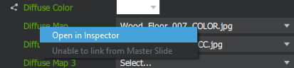
For basic and referenced materials, you need to first select the material in the scene graph. Then, right-click the map property name in the inspector and select Open in inspector from the context menu. Now the properties of the image map will show in the inspector palette.
- U/V Repeat - Controls how many copies of the image are displayed across the UV coordinates of the material. With UV Tiling set to "No Repeat" this will cause the image to only show once on a smaller portion of the material.
- Texture Mapping - Choose how the image is applied to the material:
UV Mapping- The default for diffuse and opacity maps, this causes the image to be stuck to the mesh. The same portion of the image will always appear on the same vertex (unless the UV properties are animated).Environmental Mapping- The default for specular reflection, this causes the image to be 'projected' onto the material as though it is being reflected. Using Environmental Mapping for diffuse maps provides a mirror effect.
- U/V Tiling - Controls how the image map is applied across the material when the U/V repeat values are greater than 1.
- UV Rotation - Rotates the image map around the pivot point.
- U/V Position - Slides the image map across the UV coordinates.
- U/V Pivot - Sets the pivot location in UV space.
- Minification Filter - Sets the minification filter for the Image. Setting the filter to
NearestMipmapNearest,LinearMipmapNearestorLinearMipmapLinearenables mipmapping. If the source image doesn't have mipmaps they are autogenerated. Enabling mipmapping to image with sub-presentation should be avoided since they need to be generated each time the sub-presentation is updated. - Magnification Filter - Sets the magnification filter for the Image.
- Sub-Presentation - If you specify a value here, it is intepreted to be the
idattribute of another presentation in the.uiaapplication file. Instead of displaying the contents of this image on the material, the specified presentation will be rendered and the resulting image will be used instead. For more information, see the discussion on the Using Sub-Presentations page.
Text Properties
A text element selected in the Timeline palette shows the following properties in the Inspector palette (in addition to the transform properties described above):
- Text String - The text to display for the text element.
Note: Qt 3D Studio does not (currently) support styled text. There is no way to make one word in a paragraph bold, larger, or a different color.
- Text Color - The color for the text.
- Font - Click to open a font browser. This will only look for font files inside the
fontsdirectory for your project. - Font Size - Changes the size of the font. In addition to clicking the drop-down to pick from predefined font sizes, you can also type a new value for the font.
Note: Although the font size is just a number, it is intentionally not animatable. Each time the font size changes a rather expensive rasterization of the text string occurs. You should animate the scale of the text element instead.
- Horizontal/Vertical Alignment - Controls the placement of the text with respect to the text element's origin.
Note: This is for the entire text box, and as such may include padding reserved for characters not present in your text string. For example, using the Text String "Text" with Vertical Alignment of Bottom will cause the baseline of the letters to appear above the origin for the element. Adding characters with descenders, such as "y", illustrates why this occurs.
- Leading - Controls the amount of extra (or negative) vertical spacing between lines of text.
- Tracking - Controls the amount of extra (or negative) horizontal spacing between every character pair.
- Text Area - Define size of fixed text area. If no values are set, the text size will grow with the text.
- Word Wrapping - Define how text will be wrapped when using a fixed text area size.
Clip- Cut the text if it doesn't fit in the text area.WrapWord- Wraps between words, if possible.WrapAnywhere- Wraps anywhere, also in the middle of words.
- Eliding - Elide text that does not fit into a fixed size text area.
Note: Text eliding does not work with distance field rendering disabled.
- Drop-Shadow - Add a drop shadow to the text. The drop shadow will be a darker shade of the text color.
- Shadow Darkness - Darkness of the drop shadow. 100 is black and 0 is the same color as the text.
- Horizonal Offset - Horizontal offset of the shadow. The offset is relative to the font size.
- Vertical Offset - Vertical offset of the shadow. The offset is relative to the font size.
Guide Properties
A guide selected in the scene view shows the following properties in the inspector palette:
- Position - Position of the guide, in pixels. (0,0) is the lower left corner of the scene view.
- Orientation - Orientation of the guide.
- Width - Width of the guide, in pixels.
Available under certain Qt licenses.
Find out more.