
Qt Quick 3D Physics - 복합 도형 예시
복잡한 충돌 도형 사용 방법을 보여줍니다.
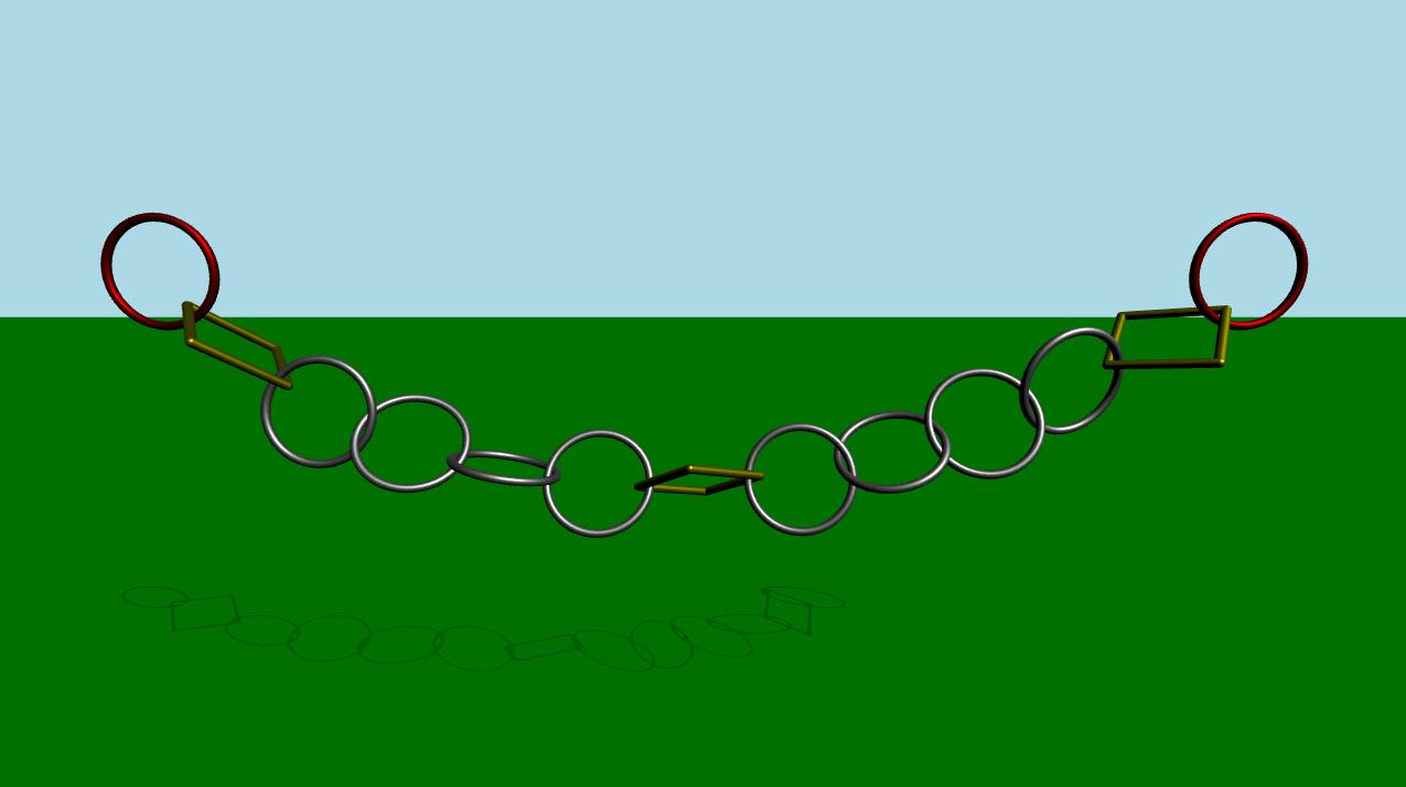
이 예제는 충돌 감지를 위해 하나 이상의 충돌 도형을 사용하여 복잡한 객체를 만드는 방법을 보여줍니다. 이 장면은 녹색의 고정된 평면과 서로 연결된 일련의 링크로 구성되어 있습니다. 처음에는 시뮬레이션이 비활성화되어 있습니다. 일정 시간이 지나거나 사용자가 스페이스 키를 누르면 시뮬레이션이 시작됩니다. 애니메이션이 시작되면 가장 왼쪽과 가장 오른쪽 링크가 수평으로 앞뒤로 움직입니다.
설정
평소와 마찬가지로 PhysicsWorld 를 추가해야 합니다:
PhysicsWorld {
    id: physicsWorld
    enableCCD: true
    maximumTimestep: 20
    scene: viewport.scene
}
환경, 카메라, 조명을 포함하는 일반적인 설정을 진행합니다:
environment: SceneEnvironment {
    antialiasingMode: SceneEnvironment.MSAA
    backgroundMode: SceneEnvironment.Color
    clearColor: "lightblue"
}

focus: true

PerspectiveCamera {
    id: camera
    position: Qt.vector3d(0, 900, 1500)
    eulerRotation: Qt.vector3d(-10, 0, 0)
    clipFar: 15500
    clipNear: 1
}

DirectionalLight {
    eulerRotation.x: -45
    eulerRotation.y: 45
    castsShadow: true
    brightness: 1.5
    shadowMapQuality: Light.ShadowMapQualityHigh
}
물리적 객체
일반적인 정적 평면이 있습니다:
StaticRigidBody {
    position: Qt.vector3d(0, -100, 0)
    eulerRotation: Qt.vector3d(-90, 0, 0)
    collisionShapes: PlaneShape {}
    Model {
        source: "#Rectangle"
        scale: Qt.vector3d(500, 500, 1)
        materials: PrincipledMaterial {
            baseColor: "green"
        }
        castsShadows: false
        receivesShadows: true
    }
}
그런 다음 링크의 인스턴스를 생성합니다.
MeshLink {
    id: leftLink
    isKinematic: true
    property vector3d startPos: Qt.vector3d(-6 * viewport.ringDistance,
                                            viewport.ringY,
                                            0)
    property vector3d startRot: Qt.vector3d(90, 0, 0)
    kinematicPosition: startPos
    position: startPos
    kinematicEulerRotation: startRot
    eulerRotation: startRot
    color: "red"
}

CapsuleLink {
    position: Qt.vector3d(-5 * viewport.ringDistance, viewport.ringY, 0)
    eulerRotation: Qt.vector3d(90, 0, 0)
}

MeshLink {
    position: Qt.vector3d(-4 * viewport.ringDistance, viewport.ringY, 0)
    eulerRotation: Qt.vector3d(90, 0, 0)
}

MeshLink {
    position: Qt.vector3d(-3 * viewport.ringDistance, viewport.ringY, 0)
    eulerRotation: Qt.vector3d(0, 90, 0)
}

MeshLink {
    position: Qt.vector3d(-2 * viewport.ringDistance, viewport.ringY, 0)
    eulerRotation: Qt.vector3d(90, 0, 0)
}

MeshLink {
    position: Qt.vector3d(-1 * viewport.ringDistance, viewport.ringY, 0)
    eulerRotation: Qt.vector3d(0, 90, 0)
}

CapsuleLink {
    position: Qt.vector3d(0, viewport.ringY, 0)
}

MeshLink {
    position: Qt.vector3d(1 * viewport.ringDistance, viewport.ringY, 0)
    eulerRotation: Qt.vector3d(0, 90, 0)
}

MeshLink {
    position: Qt.vector3d(2 * viewport.ringDistance, viewport.ringY, 0)
    eulerRotation: Qt.vector3d(90, 0, 0)
}

MeshLink {
    position: Qt.vector3d(3 * viewport.ringDistance, viewport.ringY, 0)
    eulerRotation: Qt.vector3d(0, 90, 0)
}

MeshLink {
    position: Qt.vector3d(4 * viewport.ringDistance, viewport.ringY, 0)
    eulerRotation: Qt.vector3d(90, 0, 0)
}

CapsuleLink {
    position: Qt.vector3d(5 * viewport.ringDistance, viewport.ringY, 0)
    eulerRotation: Qt.vector3d(90, 0, 0)
}

MeshLink {
    id: rightLink
    isKinematic: true
    property vector3d startPos: Qt.vector3d(6 * viewport.ringDistance,
                                            viewport.ringY,
                                            0)
    property vector3d startRot: Qt.vector3d(90, 0, 0)
    kinematicPosition: startPos
    position: startPos
    kinematicEulerRotation: startRot
    eulerRotation: startRot
    color: "red"
}
왼쪽에 있는 첫 번째 링크의 ‘ isKinematic ’ 속성은 ‘ true ’로 설정되어 있어 애니메이션을 통해 제어할 수 있습니다. 이 링크는 키네마틱 오브젝트이므로 ‘ kinematicPosition ’ 및 ‘ kinematicRotation ’ 속성을 설정해야 합니다. ‘ kinematicPosition ’ 속성을 애니메이션화하여 이 링크를 움직입니다. 나머지 링크들은 서로 간격을 두고 인스턴스화됩니다.
물리 시뮬레이션을 정확히 따르는 부드러운 애니메이션을 얻기 위해, ` PhysicsWorld`의 ` onFrameDone ` 신호에 연결된 ` AnimationController `를 사용합니다. 이렇게 하면 시뮬레이션 속도를 늦추는 프레임 드롭이 발생하더라도 애니메이션도 그에 따라 속도가 느려집니다. 가장 왼쪽과 가장 오른쪽 링을 앞뒤로 움직이기 위해 4개의 ` NumberAnimation `가 있는 ` SequentialAnimation `를 사용합니다. 다음은 애니메이션에 대한 QML 코드입니다:
Connections {
    target: physicsWorld
    property real totalAnimationTime: 12000
    function onFrameDone(timeStep) {
        let progressStep = timeStep / totalAnimationTime
        animationController.progress += progressStep
        if (animationController.progress >= 1) {
            animationController.completeToEnd()
            animationController.reload()
            animationController.progress = 0
        }
    }
}

AnimationController {
    id: animationController
    animation: SequentialAnimation {
        NumberAnimation {
            target: leftLink
            property: "kinematicPosition.x"
            to: 3 * viewport.ringDistance
            from: -6 * viewport.ringDistance
            easing.type: Easing.InOutCubic
            duration: 1000
        }
        NumberAnimation {
            target: leftLink
            property: "kinematicPosition.x"
            from: 3 * viewport.ringDistance
            to: -6 * viewport.ringDistance
            easing.type: Easing.InOutCubic
            duration: 1000
        }
        NumberAnimation {
            target: rightLink
            property: "kinematicPosition.x"
            to: -3 * viewport.ringDistance
            from: 6 * viewport.ringDistance
            easing.type: Easing.InOutCubic
            duration: 1000
        }
        NumberAnimation {
            target: rightLink
            property: "kinematicPosition.x"
            from: -3 * viewport.ringDistance
            to: 6 * viewport.ringDistance
            easing.type: Easing.InOutCubic
            duration: 1000
        }
    }
}
흥미로운 부분은 Mesh 및 Capsule Links 파일 내부에서 일어나는 일입니다. 각각을 자세히 살펴보겠습니다.
Mesh Link
DynamicRigidBody {
    id: root
    scale: Qt.vector3d(100, 100, 100)
    property color color: "white"
    PrincipledMaterial {
        id: _material
        baseColor: root.color
        metalness: 1.0
        roughness: 0.5
    }

    Model {
        source: "meshes/ring.mesh"
        materials: [_material]
    }

    collisionShapes: [
        ConvexMeshShape {
            source: "meshes/segmentedRing_001.mesh"
        },
        ConvexMeshShape {
            source: "meshes/segmentedRing_002.mesh"
        },
        ConvexMeshShape {
            source: "meshes/segmentedRing_003.mesh"
        },
        ConvexMeshShape {
            source: "meshes/segmentedRing_004.mesh"
        },
        ConvexMeshShape {
            source: "meshes/segmentedRing_005.mesh"
        },
        ConvexMeshShape {
            source: "meshes/segmentedRing_006.mesh"
        },
        ConvexMeshShape {
            source: "meshes/segmentedRing_007.mesh"
        },
        ConvexMeshShape {
            source: "meshes/segmentedRing_008.mesh"
        },
        ConvexMeshShape {
            source: "meshes/segmentedRing_009.mesh"
        },
        ConvexMeshShape {
            source: "meshes/segmentedRing_010.mesh"
        },
        ConvexMeshShape {
            source: "meshes/segmentedRing_011.mesh"
        },
        ConvexMeshShape {
            source: "meshes/segmentedRing_012.mesh"
        }
    ]
}
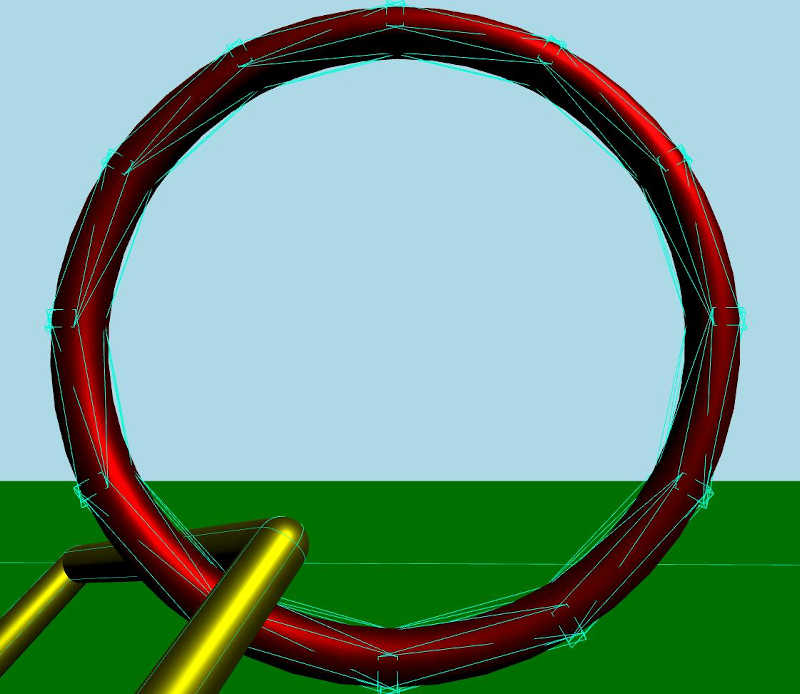
Mesh Link는 모델과 재질을 갖춘 동적 강체(Dynamic Rigid Body)입니다. 이 모델은 메시 파일에서 메시를 불러옵니다. 또한 충돌 감지를 위해 결합되어 복합 도형을 형성하는 일련의 충돌 도형 목록이 있습니다. 각 도형은 소스 파일에서 메시를 불러오는 볼록 메시(Convex Mesh) 도형입니다. 볼록 도형이란 기본적으로 도형 내의 임의 두 점 사이를 잇는 선분이 항상 도형 내부에 위치하는 도형을 말합니다.
디버그 모드를 활성화하고 자세히 살펴보면, 충돌 도형들이 복합 충돌 도형을 다음과 같이 형성하는 것을 확인할 수 있습니다:
캡슐 링크
DynamicRigidBody {
    id: root
    property real len: 170
    property real w: 17
    PrincipledMaterial {
        id: material3
        baseColor: "yellow"
        metalness: 1.0
        roughness: 0.5
    }
    Node {
        opacity: 1
        Model {
            materials: material3
            source: "#Cylinder"
            scale: Qt.vector3d(root.w / 100, root.len / 100, root.w / 100)
            eulerRotation.z: 90
            y: -root.len / 2
        }
        Model {
            materials: material3
            source: "#Cylinder"
            scale: Qt.vector3d(root.w / 100, root.len / 100, root.w / 100)
            eulerRotation.z: 90
            y: root.len / 2
        }
        Model {
            materials: material3
            source: "#Cylinder"
            scale: Qt.vector3d(root.w / 100, root.len / 100, root.w / 100)
            x: root.len / 2
        }
        Model {
            materials: material3
            source: "#Cylinder"
            scale: Qt.vector3d(root.w / 100, root.len / 100, root.w / 100)
            x: -root.len / 2
        }
        Model {
            materials: material3
            source: "#Sphere"
            scale: Qt.vector3d(root.w / 100, root.w / 100, root.w / 100)
            x: -root.len / 2
            y: -root.len / 2
        }
        Model {
            materials: material3
            source: "#Sphere"
            scale: Qt.vector3d(root.w / 100, root.w / 100, root.w / 100)
            x: -root.len / 2
            y: root.len / 2
        }
        Model {
            materials: material3
            source: "#Sphere"
            scale: Qt.vector3d(root.w / 100, root.w / 100, root.w / 100)
            x: root.len / 2
            y: -root.len / 2
        }
        Model {
            materials: material3
            source: "#Sphere"
            scale: Qt.vector3d(root.w / 100, root.w / 100, root.w / 100)
            x: root.len / 2
            y: root.len / 2
        }
    }
    collisionShapes: [
        CapsuleShape {
            y: -root.len / 2
            height: root.len
            diameter: root.w
        },
        CapsuleShape {
            y: root.len / 2
            height: root.len
            diameter: root.w
        },
        CapsuleShape {
            x: -root.len / 2
            eulerRotation.z: 90
            height: root.len
            diameter: root.w
        },
        CapsuleShape {
            x: root.len / 2
            eulerRotation.z: 90
            height: root.len
            diameter: root.w
        }
    ]
}
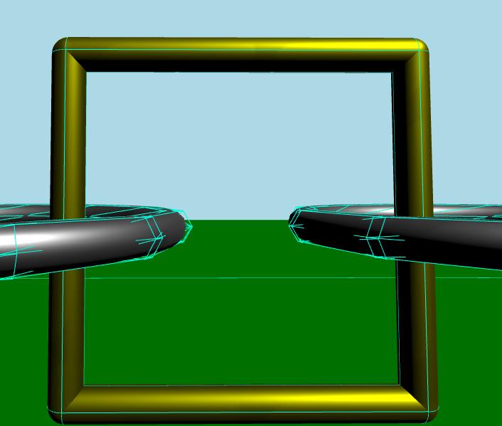
캡슐 링크는 동일한 재질을 공유하는 여러 모델로 구성된 동적 강체입니다. 이 링크는 여러 개의 원통과 구로 이루어져 있습니다. 메쉬 링크와 마찬가지로 충돌 형상의 목록이 있습니다. 이번에는 각 형상이 캡슐 형상입니다.
디버그 모드를 활성화한 상태에서 자세히 살펴보면, 충돌 형상들이 어떻게 복합 충돌 형상을 구성하는지 확인할 수 있습니다.
파일:
© 2026 The Qt Company Ltd. Documentation contributions included herein are the copyrights of their respective owners. The documentation provided herein is licensed under the terms of the GNU Free Documentation License version 1.3 as published by the Free Software Foundation. Qt and respective logos are trademarks of The Qt Company Ltd. in Finland and/or other countries worldwide. All other trademarks are property of their respective owners.
