C
Develop the Application Backend (TRAVEO T2G)
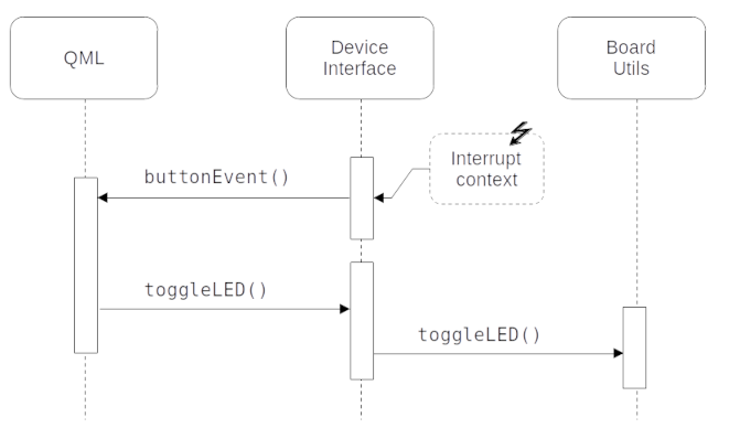
This topic guides you through the steps to create and build the application's backend using GHS MULTI IDE. The backend enables the application's UI to communicate with the platform and get the required information from the hardware. In this case, the device interface gets the status of the on-board user button. The following diagram describes the interaction between the two components:
Export application and platform sources
This section provides you step-by-step instructions to create a GHS MULTI IDE project from a QmlProject, complete with application and platform sources exported by the Qt for MCUs tools.
Note: If you are using TRAVEO T2G CYT4DN or TRAVEO T2G Cluster 4M Lite Kit, replace tviic2d4m-baremetal with tviic2d6m-baremetal or tviic2d4mlite-baremetal respectively in the following steps.
- Create a batch script with the following commands, which calls the
qmlprojectexporterto generate a GHS Multi IDE projectset QUL_ROOT=C:\path\to\QtMCUs\2.12.2 set QMLPROJECT_FILE=C:\path\to\YourProject.qmlproject set BOARDDEFAULTS=%QUL_ROOT%\platform\boards\cypress\tviic2d4m-baremetal\cmake\BoardDefaults_32bpp.qmlprojectconfig set GRAPHICS_DRIVER_DIR=C:\path\to\TVII-GraphicsDriver-V2.4.0 set PROJECT_DIR=C:\path\to\PROJECT_DIR %QUL_ROOT%\bin\qmlprojectexporter.exe %QMLPROJECT_FILE% --platform=tviic2d4m-baremetal --toolchain=ghs-arm --boarddefaults=%BOARDDEFAULTS% --outdir=%PROJECT_DIR% --project-type=ghs --include-ide-generated-hw-code --board-sdk=%GRAPHICS_DRIVER_DIR%Before running the script, make sure that the following variables are set:
GRAPHICS_DRIVER_DIRto the TRAVEO T2G Graphics Driver install path,QUL_ROOTandQMLPROJECT_FILE.PROJECT_DIRto the output directory where you want to place the GHS project files.
Now, run the script from the command prompt to generate the following:
- C++ sources generated from QML in
%PROJECT_DIR%/QtMCUs/generated - The exported platform sources in
%PROJECT_DIR%/QtMCUs/platform - A top-level project file with subproject files in
%PROJECT_DIR%/GHS.
The generated GHS project includes the following:
%PROJECT_DIR%/GHS/project.gpj: The top-level project file.%PROJECT_DIR%/GHS/prj/program.gpj: The program compile definitions, include directories, compiler and linker options.%PROJECT_DIR%/GHS/prj/drivers.gpj: List of the TVII Graphics Driver sources.%PROJECT_DIR%/GHS/prj/QtMCUs/qul_platform.gpj: List of the TRAVEO T2G CYT3DL platform sources.%PROJECT_DIR%/GHS/prj/QtMCUs/qul_app.gpj: List of the generated sources from the main.qmlprojectfile.%PROJECT_DIR%/GHS/prj/QtMCUs/qul_module_<ModuleName>.gpj: One subproject for each module, including the sources generated for the corresponding module.qmlprojectfile.%PROJECT_DIR%/GHS/prj/application.gpj: A convenience empty subproject for the application, which you will edit in the next section.%PROJECT_DIR%/GHS/mcu_<YourProject>_qul_workspace.gmb: A workspace with some added commands for convenience. See GHS Multi IDE QUL Workspace for more details.%PROJECT_DIR%/GHS/qul_flash_jlink.bat: A batch file to flash the application using the J-Link probe.%PROJECT_DIR%/GHS/qul_flash_miniprog.bat: A batch file to flash the application using the MiniProg4 probe.
For more information, refer to Exporting a Qt for MCUs project with platform sources.
Build application in GHS MULTI IDE
The following instructions guide you through the GHS project adaptation steps needed to build the application:
- Launch the GHS MULTI Launcher (
mstart.exe) - Select File > Load Workspace from File... and navigate to %PROJECT_DIR%/GHS as exported in the previous section. Select the workspace file
mcu_<YourProject>_qul_workspace.gmb. - Double-click the Project Manager entry in the workspace to open the project in the Project Manager.
- Create a new file named
main.cppin any directory. The directory will be referred to as BACKEND_DIR:#include "YourProject.h" #include <qul/application.h> #include <qul/qul.h> int main() { Qul::initHardware(); Qul::initPlatform(); Qul::Application app; static YourProject item; app.setRootItem(&item); app.exec(); return 0; }This file has the default entrypoint for the application. You will extend this entrypoint later with extra configuration steps to use the LED and user button. Refer to the running Qt Quick Ultralite in applications documentation for more information. Make sure to use the same project name (YourProject) that you chose in the earlier chapter.
- Select and hold or right-click
application.gpjand select Edit. Replace its contents with the following.#!gbuild macro APPLICATION_EXPORT_DIR=C:/path/to/PROJECT_DIR/QtMCUs/generated macro BACKEND_DIR=C:/path/to/BACKEND_DIR [Subproject] -DQUL_STD_STRING_SUPPORT -I${APPLICATION_EXPORT_DIR} # ----- backend ----- ${BACKEND_DIR}/main.cppMake sure to set the
APPLICATION_EXPORT_DIRmacro to the directory that has the exported UI sources, and the BACKEND_DIR macro to the directory containing the backend sources andmain.cpp.Note: Indentation is important in
.gpjproject files. Make sure there is no whitespace in the beginning of the line including the source file. Refer to the MULTI IDE documentation for more information. - The application binary name is
application.elfby default. To use a different name, change-o application.elfto-o YourProject.elfin theprogram.gpjproject file. - At this point, to verify that the steps so far have been followed correctly, you can build your partially implemented application and flash it to the TRAVEO T2G board using the GHS MULTI IDE workspace shortcuts to the helpful batch files that the
qmlprojectexportergenerated while exporting the project.Note: The TRAVEO T2G Cluster 4M Lite (KIT_T2G_C-2D-4M_LITE) platform port board defaults to USB display output, see Display output (TRAVEO T2G CYT3DL 4M LITE KIT and CYT4DN 6M LITE KIT) for more information.
The batch files (
qul_flash_jlink.batandqul_flash_miniprog.bat) are placed in the same directory as the main project file, and they include the commands used for flashing the application using either the J-Link or MiniProg4 probe.You can run the batch file corresponding to your probe directly from the GHS MULTI IDE workspace.
Note: For details on the commands run from these batch files, see Flashing Instructions for Infineon boards.
The batch file assumes that the Infineon Auto Flash Utility 1.4 is installed in the default location, or that its path is stored in the environment variable
INFINEON_AUTO_FLASH_UTILITY_DIR.You will also need to flash a bootloader to the CM0+ core of the TRAVEO T2G board. For detailed instructions, see Bootloader Flashing Instructions for Infineon boards.
In the next section, you will add the logic to enable interaction between the application UI and hardware with the user button.
Develop the C++ backend
The following instructions guide you through the process of developing the C++ backend for your application:
- Create new C++ source and header files and name them
deviceinterface.cppanddeviceinterface.hrespectively. Save these files in the BACKEND_DIR directory that you just created. - Replace the contents of
deviceinterface.hwith the following:#ifndef DEVICEINTERFACE_H #define DEVICEINTERFACE_H #include <qul/signal.h> #include <qul/singleton.h> #include <qul/eventqueue.h> typedef int HWButtonEvent; class DeviceInterface : public Qul::Singleton<DeviceInterface>, public Qul::EventQueue<HWButtonEvent> { public: Qul::Signal<void(int button)> buttonEvent; void onEvent(const HWButtonEvent &inputEvent); void toggleLED(); }; #endif //DEVICEINTERFACE_HThe header declares the
DeviceInterfaceclass, which inherits from Qul::Singleton and Qul::EventQueue. It also declares thebuttonEventSignal and theHWButtonEventevent type. This allows the Singleton instance to be globally available. It provides an interface between C++ and QML, to emit the changed signal on receiving theHWButtonEventinput event. For more information, refer to Defining Singletons in QML and Transferring data from Interrupt Handlers to QML. - Similarly, replace the contents of
deviceinterface.cppwith the following:#include "deviceinterface.h" #include "boardutils.h" #include <platforminterface/log.h> extern "C" void DeviceInterface_handleButtonEvent() { DeviceInterface::instance().postEventFromInterrupt(0); } void DeviceInterface::onEvent(const HWButtonEvent &inputEvent) { buttonEvent(inputEvent); } void DeviceInterface::toggleLED() { Qul::PlatformInterface::log("Toggling LED\n"); BoardUtils_toggleLED(); } - Create new C source and header files and name them
boardutils.candboardutils.hrespectively. Save these files in the BACKEND_DIR directory. - Replace the code in
boardutils.hwith the following:#ifndef BOARDUTILS_H #define BOARDUTILS_H #ifdef __cplusplus extern "C" { #endif void BoardUtils_configure(); void BoardUtils_toggleLED(); #ifdef __cplusplus } #endif #endif //BOARDUTILS_H - Add the TRAVEO T2G specific implementation of
BoardUtils_configure()andBoardUtils_toggleLED()toboardutils.c:#include "boardutils.h" #include <stdint.h> #include <cy_project.h> #define USER_LED1_PORT CY_USER_LED1_PORT #define USER_LED1_PIN CY_USER_LED1_PIN #define USER_LED1_PIN_MUX CY_USER_LED1_PIN_MUX #define USER_BUTTON1_PORT CY_USER_BUTTON_WAKE_PORT #define USER_BUTTON1_PIN CY_USER_BUTTON_WAKE_PIN #define USER_BUTTON1_PIN_MUX CY_USER_BUTTON_WAKE_PIN_MUX #define USER_BUTTON1_IRQN CY_USER_BUTTON_WAKE_IRQN extern void DeviceInterface_handleButtonEvent(); void ButtonInterruptHandler(void) { uint32_t interruptStatus = Cy_GPIO_GetInterruptStatusMasked(USER_BUTTON1_PORT, USER_BUTTON1_PIN); if (interruptStatus) { DeviceInterface_handleButtonEvent(); Cy_GPIO_ClearInterrupt(USER_BUTTON1_PORT, USER_BUTTON1_PIN); } } void BoardUtils_configure() { // GPIO configuration for LED cy_stc_gpio_pin_config_t user_led_port_pin_cfg = { .outVal = 0x00, .driveMode = CY_GPIO_DM_STRONG_IN_OFF, .hsiom = USER_LED1_PIN_MUX, .intEdge = 0, .intMask = 0, .vtrip = 0, .slewRate = 0, .driveSel = 0, .vregEn = 0, .ibufMode = 0, .vtripSel = 0, .vrefSel = 0, .vohSel = 0, }; Cy_GPIO_Pin_Init(USER_LED1_PORT, USER_LED1_PIN, &user_led_port_pin_cfg); // GPIO configuration for button static cy_stc_gpio_pin_config_t user_button1_port_pin_cfg = { .outVal = 0x00, .driveMode = CY_GPIO_DM_HIGHZ, .hsiom = USER_BUTTON1_PIN_MUX, .intEdge = CY_GPIO_INTR_FALLING, .intMask = 1, .vtrip = 0, .slewRate = 0, .driveSel = 0, .vregEn = 0, .ibufMode = 0, .vtripSel = 0, .vrefSel = 0, .vohSel = 0, }; Cy_GPIO_Pin_Init(USER_BUTTON1_PORT, USER_BUTTON1_PIN, &user_button1_port_pin_cfg); // IRQ configuration for button cy_stc_sysint_irq_t irq_cfg = { .sysIntSrc = USER_BUTTON1_IRQN, .intIdx = CPUIntIdx2_IRQn, .isEnabled = true, }; Cy_SysInt_InitIRQ(&irq_cfg); Cy_SysInt_SetSystemIrqVector(irq_cfg.sysIntSrc, ButtonInterruptHandler); NVIC_SetPriority(CPUIntIdx2_IRQn, 3); NVIC_ClearPendingIRQ(CPUIntIdx2_IRQn); NVIC_EnableIRQ(CPUIntIdx2_IRQn); } void BoardUtils_toggleLED() { Cy_GPIO_Inv(USER_LED1_PORT, USER_LED1_PIN); }The configure function initializes the LED and button pins. It then registers
ButtonInterruptHandler()as the interrupt request handler for the user button events using the GPIO and IRQ APIs from the TRAVEO T2G Graphics Driver.Note: After implementing the backend logic, press the SW5 hardware button on the board to trigger the button event.
- To properly configure the TRAVEO T2G LED and button, change
main.cppto include theboardutils.hheader and to callBoardUtils_configure()after the normal platform initialization:#include "boardutils.h" ... int main() { Qul::initHardware(); Qul::initPlatform(); BoardUtils_configure(); ... } - Add the new source files to
application.gpj:#!gbuild ... # ----- backend ----- ${BACKEND_DIR}/main.cpp ${BACKEND_DIR}/boardutils.c ${BACKEND_DIR}/deviceinterface.cpp
Integrate UI and backend in Design Studio
Use the DeviceInterface Singleton object from Qt Design Studio, to access the low-level backend functions that you implemented in the earlier section.
- Open your project in Qt Design Studio and select the Connections view.
- Select the
 button in the Connections tab
  to add a new connection.
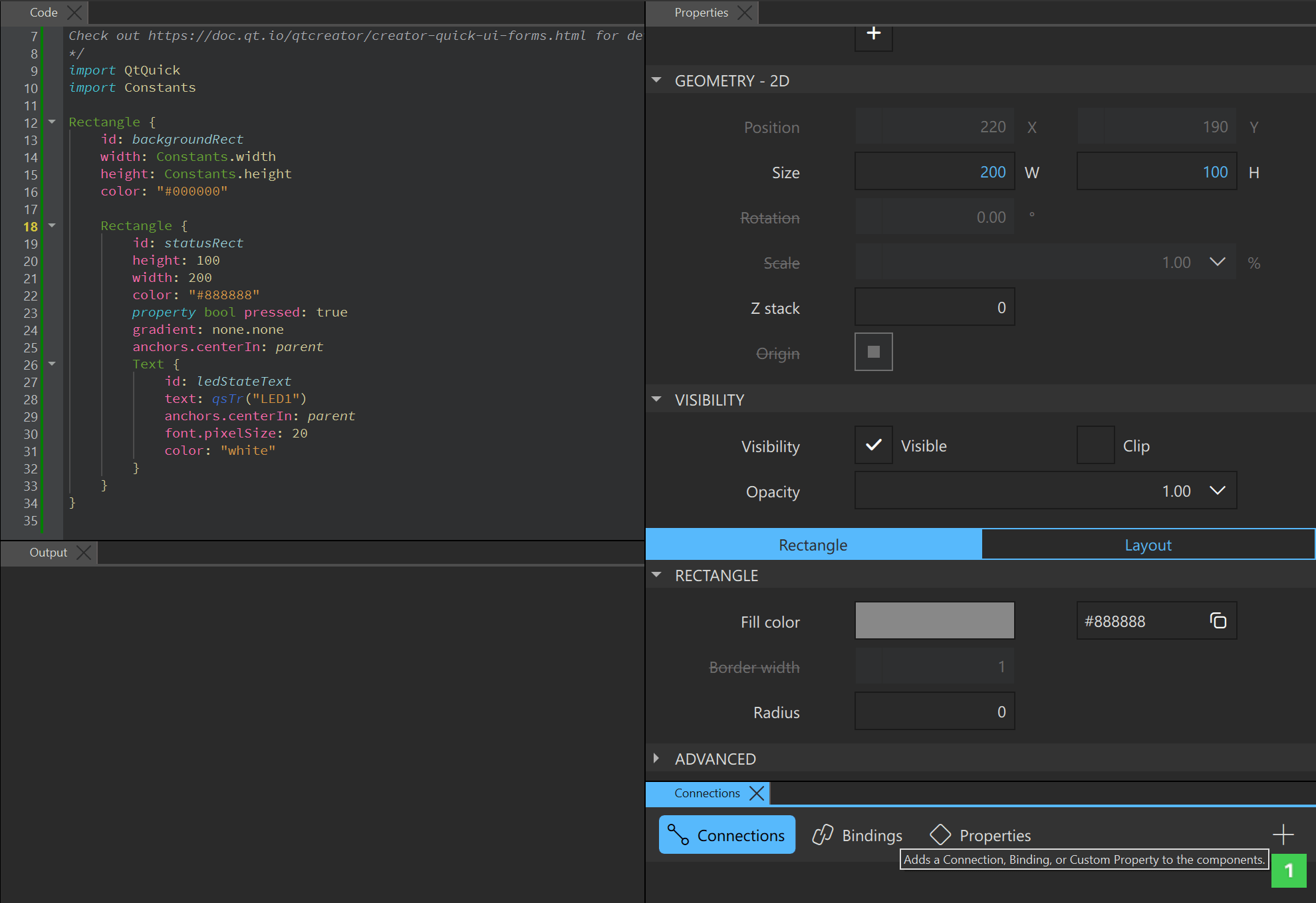
- Select the new connection and use the Connection panel
 to jump to the Code view.
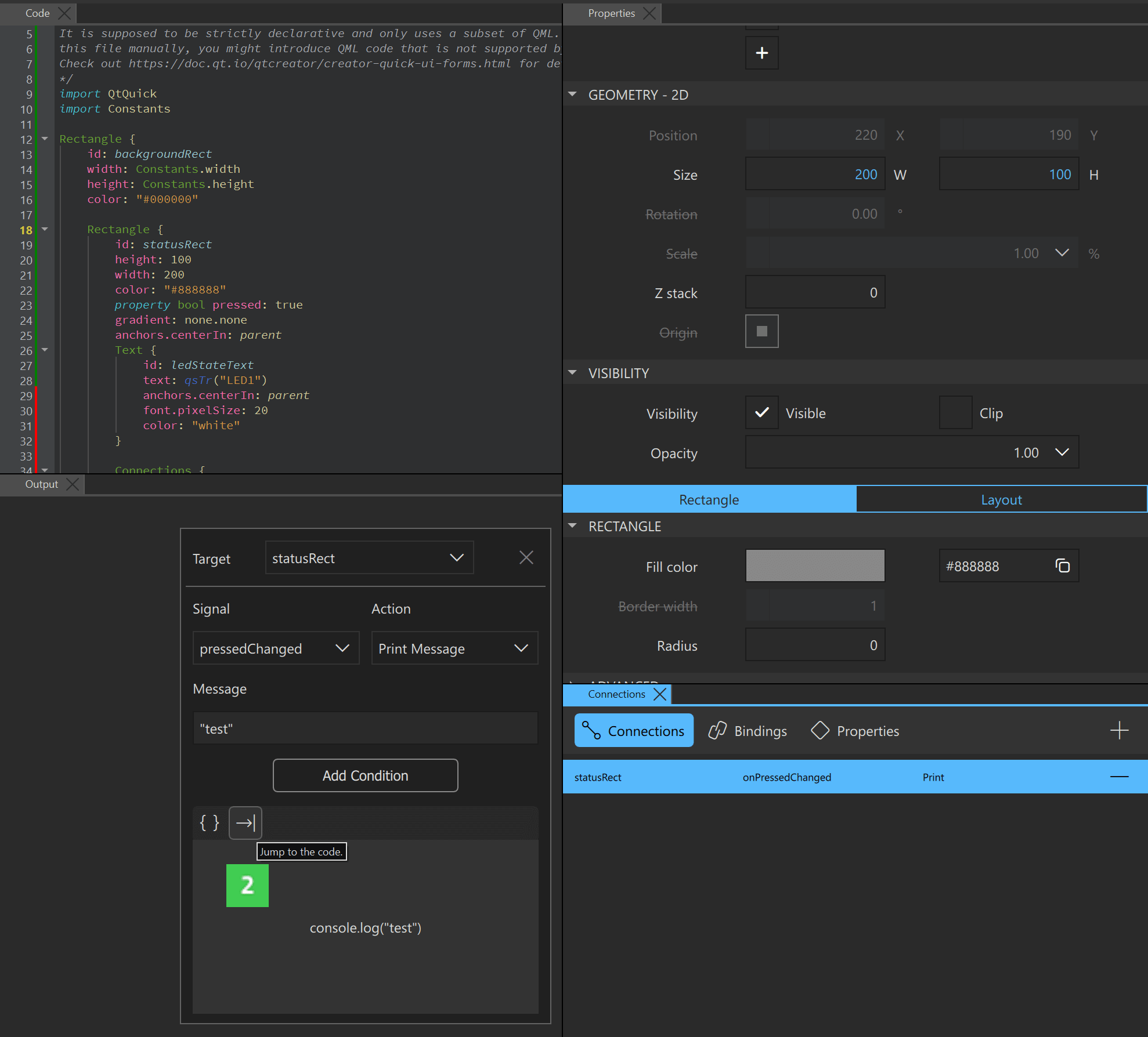
- In Code view, add the first connection
 with
with statusRectas thetarget, andDeviceInterface.toggleLED()as the action for theonPressedChangedsignal.
- In Code view, add the second connection
 with
with DeviceInterfaceas thetarget, andstatusRect.pressed = !statusRect.pressedas the action for theonButtonEventsignal.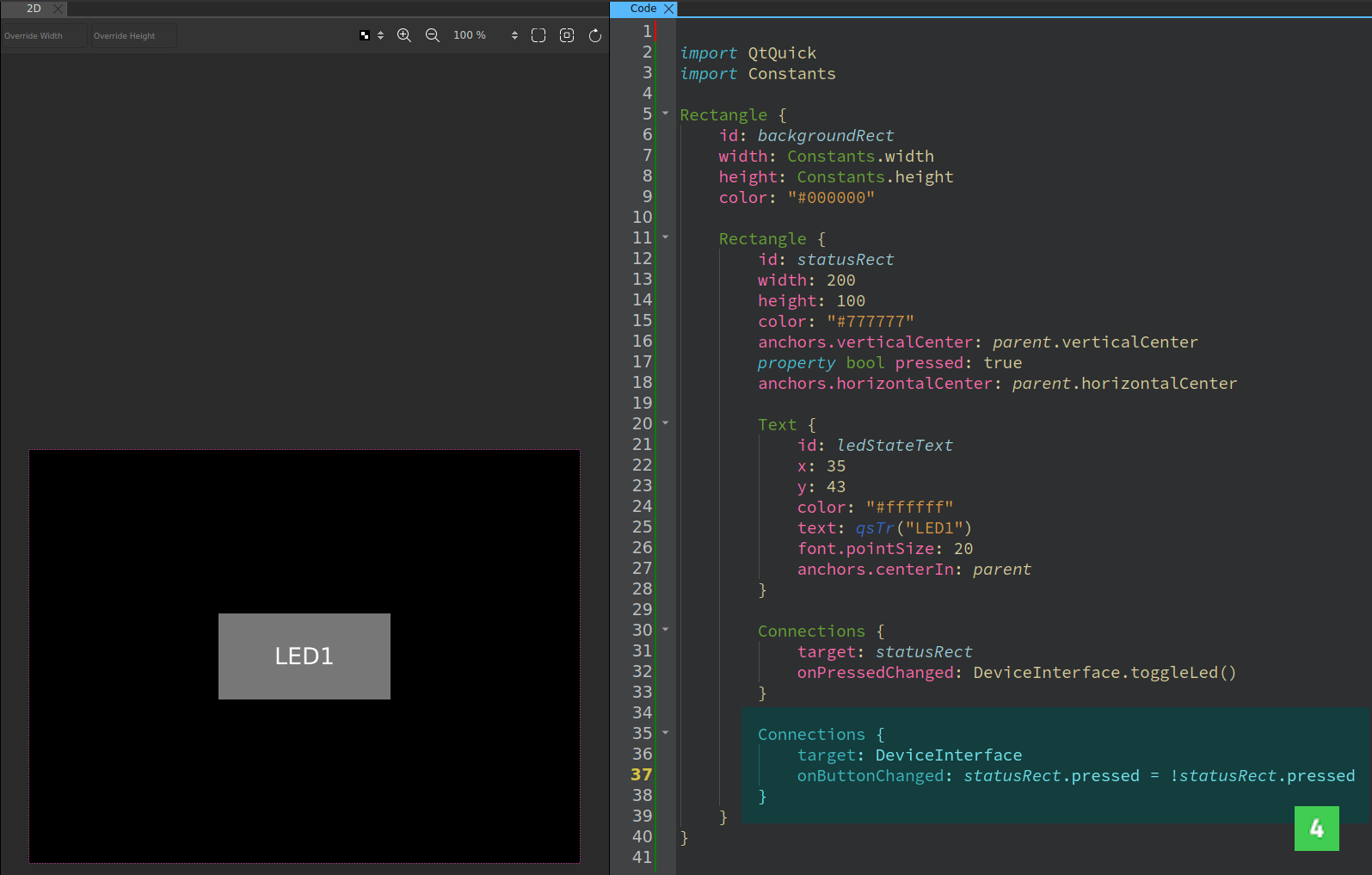
Now when you press the button, the event propagates to the QML context, which changes the
statusRect.pressedproperty. This results in changing the color of the UI item. In response to thestatusRect.pressedproperty change, theDeviceInterface.toggleLED()method toggles the LED. - Use a text editor to change
yourproject.qmlprojectto generate the necessary C++/QML interfaces needed for the singleton object:InterfaceFiles { files: ["C:/path/to/BACKEND_DIR/deviceinterface.h"] }Change the BACKEND_DIR path to the directory containing the
deviceinterface.hfile.For more information, refer to QmlProject InterfaceFiles.
Update the GHS project after making changes to the UI
Since you have made changes to the UI parts of your application, export the UI sources again using qmlprojectexporter.
Use the --update-project command-line argument to apply new changes in UI code to an existing GHS project. Use one of the methods listed below:
- Use the predefined command under
Sync Qmlproject filesin the workspace in the GHS MULTI Launcher. Double-click it in the UI to update the project files. - Manually invoke
qmlprojectexporterusing the following batch script:set QUL_ROOT=C:\path\to\QtMCUs\2.12.2 set QMLPROJECT_FILE=C:\path\to\YourProject.qmlproject set PROJECT_DIR=C:\path\to\PROJECT_DIR set QMLPROJECT_DIR=%PROJECT_DIR%\QtMCUs\generated %QUL_ROOT%\bin\qmlprojectexporter.exe %QMLPROJECT_FILE% --update-project=%PROJECT_DIR%/GHS/project.gpj
Available under certain Qt licenses.
Find out more.
