
5.9.4. Editing the Graph
The operations described here are accessible in both hierarchical and flat graph windows.
Graph elements can be created
by a source code analysis,
by further automated analyses,
by imports from external tools (like UML tools),
and manually by the user.
Graph elements are created manually using the 
Node Tool and the

Edge Tool from the Toolbox. The currently
selected type of element in the palette windows will be used for creation.
5.9.4.1. Creating Nodes
Activate the Node Tool, select the desired node type from the
Node Types palette and click inside the graph window where the new node
shall be placed.
A new node icon appears at the position of the click and the Create node
dialog pops up asking for the name of the new node. The supplied node name is taken as
value for the attribute Source.Name of the new node. The new node
automatically gets a unique random value for its attribute Linkage.Name.
Note
Holding down Shift while clicking bypasses the renaming dialog. This can be
useful when wanting to create several nodes in one go. The nodes can be renamed later
using 
Edit → Rename... from
the context menu.
Note
You can reset the unique random linkage name applied to the node by selecting the
node and choosing Edit → 
New selection identity. This unlinks it from nodes in existing GXL
files and layouts and gives it a new identity.
Creating a new node anywhere inside a target node, including on its node symbol, makes the new node a child of the target node. A collapsed target node is expanded, so the new node is visible. While moving the mouse pointer, the current target node is highlighted. Placing a node on the graph background, where no node is highlighted, makes it a top-level node.
If the node inside which you want to create a child node is currently collapsed, you can expand it by double-clicking on it. See section Expanding and Collapsing Nodes.
Dragging from the Node Types palette
Instead of activating the Node Tool, you can drag a node type
icon from the Node Types palette into the graph window and drop it where
the new node shall be placed. This creates a node in the same way as clicking with the
Node Tool does, including the highlighting of the target area
and the subsequent Create node dialog, which can be bypassed by holding
down Shift while dropping.
Spring-loaded expansion
While dragging a node type icon, resting the mouse pointer over a collapsed node expands
that node, so a new node can be created inside it without expanding it beforehand. Moving
the pointer out of the node without releasing the mouse button collapses it again. This
works to any depth. Once a node has expanded, you can rest the pointer over one of its
children to expand that one, and carry on until you have reached the node you want to
create the new node in. The time the pointer has to rest over the node is set by the
option /Tools/Gravis/node_tool/spring_load_delay in axivion_config. Set
this option to 0 to switch automatic expansion off.
Note
After you have created a new node, it shows up at an arbitrary position in all other opened windows that show the same view and in which the node’s parent is expanded.
5.9.4.2. Editing the Hierarchy
To relocate nodes within the node hierarchy, activate the

Hierarchy
Tool
. It allows you to move nodes from one parent
to another by dragging them to the expanded node area of the desired new parent node. A
drag onto the window background makes the dragged node a top-level node.
When holding down the Shift key, the drag includes all sibling nodes with the same selection/marking state as the dragged node. For instance, dragging a selected node with Shift held down drags all selected nodes found within the same parent.
While you drag, the target area representing the new parent node is highlighted.
Note
The prospective new parent node has to be expanded already before the drag operation is started.
Note
You can select and deselect nodes in the Hierarchy Tool
in the same way as in the 
Select Tool without having to
switch tool.
5.9.4.3. Creating Edges
Activate the Edge Tool, select the desired edge type from the
Edge Types palette. First, select the source node of the new edge by
clicking on it. The source node gets highlighted and a rubber band style edge appears. A
click on some other node selects the target node and creates the edge. Clicking with the
right mouse button or pressing Escape cancels the operation.
Note
The newly created edge automatically appears in all other windows showing the same view, provided that both its source and target nodes are currently displayed.
Note
If you create an edge of the same type between the same node twice, there is a warning allowing you to cancel the operation.
It is not possible to redirect an existing edge, i. e. change its source or target node. In order to do that, it is necessary to remove the existing edge and create a new one in its place.
Note
Adding a hierarchical edge is not possible in the Edge Tool.
The hierarchy can only be edited using the Hierarchy
Tool. This ensures the integrity of the hierarchical structure by making it
impossible to create cycles by accident.
5.9.4.4. Editing Edges
The Edge Tool can also be used to edit existing edges. To
change the source or target node of an edge, move the pointer over the edge near its
start or end. The pointer shape changes into four arrows to indicate that the edge
endpoint can be changed. Press and hold the left mouse button to drag the edge’s
endpoint over a different node. During the drag potential node targets are highlighted
as the pointer is moved over them. Release the mouse button while a node is highlighted
to confirm the new endpoint. The edge is re-routed from/to its new source/target node.
If you release the mouse button over empty space the edge reverts to its original
location.
The direction of an edge can be reversed using
Edit → 
Reverse edge from
its context menu. If the edge occurs in more than one view this changes the edge in all
views, so there is an extra confirmation step in this case.
5.9.4.5. Creating and Editing Notes
Notes, sometimes also called comments, are useful for documentation purposes, in particular in architecture diagrams. They can be used to add extra information to the diagram as a whole or to individual nodes.
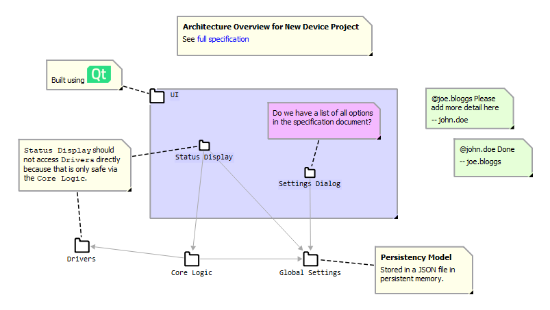
An example diagram using notes
Adding notes to your diagram
Attaching a note to a node
To create a new note linked to an existing node, open the context menu over the node and
choose Edit → 
Add note.... This
opens the Notes Editor, a rich text editor window, in which you can
compose the note. See The Notes Editor below for how to
use the Notes Editor.
After clicking on Insert note in the Notes Editor, the note appears close
to the node it refers to. It is linked to the node with a dashed line.
The note is actually an ordinary node of type UML Note in the graph
and responds to all Gravis features affecting nodes like layouts, selection operations,
etc. The dashed line linking it to its associated node is an ordinary edge of type
UML NoteLink.
Adding free notes
To create a free top-level note that is not linked to any node, open the context menu
over the window background and choose Edit →
Add note.... Free notes are useful for headings or general information
about a diagram. They can also be used inside components to add general information. To
add a free note inside a component, create it at the top level, then move it inside the
component using the Hierarchy Tool (see
Editing the hierarchy).
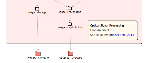
A free note inside a component
Repositioning, resizing and collapsing notes
You can reposition and resize the note using the usual Gravis features just like
any other node: By dragging the note itself or its resize handle in a suitable tool,
e. g., Navigator or Selector.
To save space, you can collapse a note by double-clicking on it. To re-expand it, double-click on it one more time.
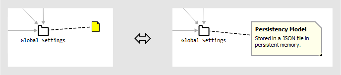
A note in collapsed and expanded state
You can link a note to a different node by retargeting the linking edge using the
Edge Tool (see Editing Edges).
You can turn a linked note into a standalone note by deleting the linking edge. To do
this, open the context menu over the edge and choose Edit →

Delete.
You can link a note to as many nodes as you like by creating additional
UML NoteLink edges using the Edge Tool.
Sometimes it is useful to have a link between a note and a node that is not displayed
but that is still there and can be retrieved when needed. You can achieve that by
hiding the linking edge instead of deleting it (see
Hiding Elements). You can find out to which node the
note is linked without unhiding the edge using 
Visualization → 
Focus on node (see
Focus on Nodes).
Hint
Since notes are ordinary nodes, nothing stops you from adding a note to a note.
Editing a note
To edit a note, open the context menu over the note and choose
Edit → 
Edit text... or simply double-click
on the note while holding down the Shift key. This opens the
Notes Editor window.
The Notes Editor
The Notes Editor is used to create and edit notes. It offers standard text
editing features. While editing all changes can be undone and redone using the  undo and
  redo buttons (keyboard shortcuts Ctrl+Z and Ctrl+Y respectively).
When invoked via
redo buttons (keyboard shortcuts Ctrl+Z and Ctrl+Y respectively).
When invoked via Add note..., clicking on Insert note
inserts the new note into the diagram. When invoked via Edit text...,
clicking on Update note updates the edited note in the diagram. Clicking
on Cancel closes the dialog without changing the diagram.
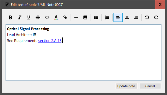
The Notes Editor
Text character properties
There are the following controls for changing text character properties:
|
Make the selected text bold. |
|
Make the selected text italic. |
|
Underline the selected text. |
|
Strike out the selected text. |
|
Display the selected text in a monospace font (e. g., for code references). |
|
Change the color of the selected text. |
|
Enter a URL to turn the selected text into a link. |


If any of the controls are used while there is no text selection, the properties are set on the caret and applied to text that is subsequently entered.
Text paragraph properties
There are the following controls for changing text character properties:
|
Turn the paragraphs into a list with bullets. |
|
Turn the paragraphs into a list with numbers. |
|
Make the paragraphs left aligned. |
|
Make the paragraphs centered. |
|
Make the paragraphs right aligned. |


If any of the controls are used while there is no text selection, the properties are applied to the paragraph containing the caret.
Inserting rules and images
Click on  to insert a horizontal line between paragraphs.
Click on  to insert an image into the text. This opens a file chooser
that allows you to browse for an image file in JPEG, PNG or SVG format. After a suitable
image file has been chosen, the
to insert an image into the text. This opens a file chooser
that allows you to browse for an image file in JPEG, PNG or SVG format. After a suitable
image file has been chosen, the Insert image dialog is shown:
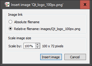
You can insert the image using an absolute or relative filename reference. The absolute
filename can be seen by hovering the mouse pointer over the Absolute
filename option. The relative filename is displayed next to Relative
filename:. By default a relative reference is used, if possible. If the graph has not
been saved yet, the only available option is an absolute reference. Graph files with
relative image references can be moved between platforms and systems just by making sure
that both the graph file and the referenced images are transferred at the same time
keeping their relative positions in the filesystem. The downside of relative references
is that they may become outdated if the graph file is moved within the file hierarchy
without moving the images.
The Scale image size section allows you to control the size at which the
image is inserted. Please note that the absolute width and height are stored in the
note, so if the dimensions of the referenced image file change afterwards, then the
changed image will be squashed into the rectangle that was originally set up here.
Customizing Notes
To change the background color of a note, choose
Visualization → 
Node color... from the
context menu over the note. See Expanded area color.
To make the text in the note smaller or bigger, choose
Visualization → 
Base font size... from
the context menu over the note and enter a different font size in points. This value is
specific to the current diagram and stored in saved layouts.
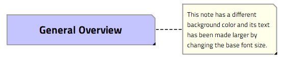
A customized note
5.9.4.6. Deleting Elements
A single graph element is deleted using
Edit → Delete from its context
menu.
Multiple graph elements are deleted in one go by first selecting them and then using
Edit → 
Delete
selection
from the graph window context menu.
See Section Working with Selections and the Marking.
5.9.4.7. Editing Attributes
Editing Node Names
The name of a node (i. e. the value of its Source.Name attribute) can be
changed by Edit → Rename... from
the context menu of the node or by pressing F2 while the pointer is over the node.
The name can also be edited directly on the canvas: Click the node and then click its name, leaving enough time between the two clicks for them to not be taken for a double click. An edit field opens on top of the name. Press Enter or click elsewhere to store the new name, Esc to discard it. An empty name is discarded as well. This works for node types that show the node name below the node, which is the default. It does not work for node types that have been configured to show something else there, e. g. the value of a different attribute.
A name that contains line breaks is shown over several lines. Since Enter ends the edit, line breaks cannot be added on the canvas, except by pasting them in.
Editing Arbitrary Attributes
All attributes can be inspected, added, changed, and removed by

Open → 
Node
Information...
and
Open → Edge
Information..., respectively. This dialog contains an attribute area that displays the
values of all set attributes. The attributes are shown as a hierarchical tree. Dots in
the attribute names separate levels, e. g., the attributes Source.File,
Source.Line and Source.Name are shown as File, Line and
Name under a common parent item Source.
Editing Attribute Values
Choosing Edit... from the context menu or double clicking a row opens the
Edit attribute dialog which allows changing the value of the selected
attribute.
Note
A toggle attribute (boolean flag) does not allow its value to be changed. The only way to edit it is to remove it.
Caution
The identities of graph elements are defined by their attributes. Changing the
values of certain attributes (most notably Linkage.Name) may change a
node’s identity so that GXL files and layouts do not refer to that node any more.
Deleting Attributes
An attribute can be removed by choosing Delete from its context menu.
Adding Attributes
An attribute that is not present yet can be added by choosing Add
attribute... from the context menu over the attribute area. After choosing the
attribute key (i. e., the name of the attribute) from the drop-down menu of the
Key: field, the Type: field displays the type of the
attribute. Enter the desired value into the Value: field and click on
OK to add the attribute.