
5.9.6. Architecture Analysis Facilities
Architecture analysis basically checks whether two views match in structure. In this process, one view represents the architecture and the other view represents the implementation of that architecture. Three pieces of input data are needed for the check: The two views to check and a mapping between them. The mapping is also represented as a view. In the explanation of the interactive architecture analysis features provided by Gravis, it is assumed that a software architecture is to be checked against code. Nevertheless, architecture analysis can also be used for other purposes, e. g., model-to-model checking.
The Architecture Guide describes the general architecture analysis approach and typical Gravis usage scenarios. This section focuses on the Gravis user interface.
Note
The view that represents the implementation can either be a single view in the RFG or
the combination of two views: a hierarchy view that just specifies the hierarchical
nesting of source code entities and a base view that specifies the dependencies
between them. Whether there is a single view or two views depends on the programming
language from which the RFG was created: Source code analysis of C# and Rust produces
a single view, whereas analysis of C/C++ code produces separate views for the
hierarchy and the dependencies. There are even two alternative combinations of
views that can be used: Code Facts as base view with Module
as hierarchy view or Declaration Facts as base view with
File as hierarchy view. Similarly, C# analysis produces two alternative
views that can be used: Code Facts or Assembly. Which of
these two views or combinations of views is the most suitable depends on the way the
software is designed and the architectural properties that should be checked.
The choice of views is discussed in more detail in the section Creating the Mapping in the Architecture Guide.
The views that take part in the analysis are to be assigned roles:
 Architecture,
  Mapping,
 Hierarchy, and
  Base. The last two roles are used
for the code (the implementation). In case that only one view represents the code under
analysis, the Hierarchy role has to be assigned. In case of two
views, the role Hierarchy is assigned to the view containing the
hierarchy used for mapping whereas the Base role is assigned to the view
that contains the relationships among the entities in the code.
Base. The last two roles are used
for the code (the implementation). In case that only one view represents the code under
analysis, the Hierarchy role has to be assigned. In case of two
views, the role Hierarchy is assigned to the view containing the
hierarchy used for mapping whereas the Base role is assigned to the view
that contains the relationships among the entities in the code.
In the following, the view to which the Architecture role is
assigned is referred to as architecture view, the view to which the
Hierarchy role is assigned to is referred to as hierarchy view,
and the view to which the Mapping role is assigned to is referred to
as mapping view.
Note
The mapping view contains nodes from the architecture view and the hierarchy view.
Additionally, the mapping contains 
Maps_To edges from
nodes in the hierarchy to nodes in the architecture. As an alternative to the
dedicated Mapping Window described in the next section, it is possible to review and
edit the mapping view in an ordinary Graph Window using the menu entry

Open → 
Flat...
from the view’s context menu in the 
View Box or by
double-clicking on the view while the Mapping role is not assigned to it.
5.9.6.1. Mapping Window
The Mapping Window offers comfortable facilities for reviewing and editing the mapping
between the source code and the architecture. The Architecture,
Mapping, and Hierarchy roles need to be assigned
prior to opening the Mapping Window. It is opened by either double clicking on the view
with the role Mapping in the View Box, or by
choosing either Edit → 
Architectural
mapping
→ 
Architecture as tree or
Edit → Architectural
mapping → 
Architecture as graph from
the main menu, or by choosing either

Open → Mapping
with architecture as tree... or
Open → Mapping
with architecture as graph... from the context menu over the view with the role
Mapping in the View Box.
The Mapping Window is split in two sections. The left one shows the hierarchy view as a tree, the right one shows the architecture view, either as a tree or as a graph.
Note
If the architecture is shown as a tree, notes are left out, because their contents cannot be displayed in a tree and there is no point in mapping source code to a note. They are shown if the architecture is displayed as a graph.
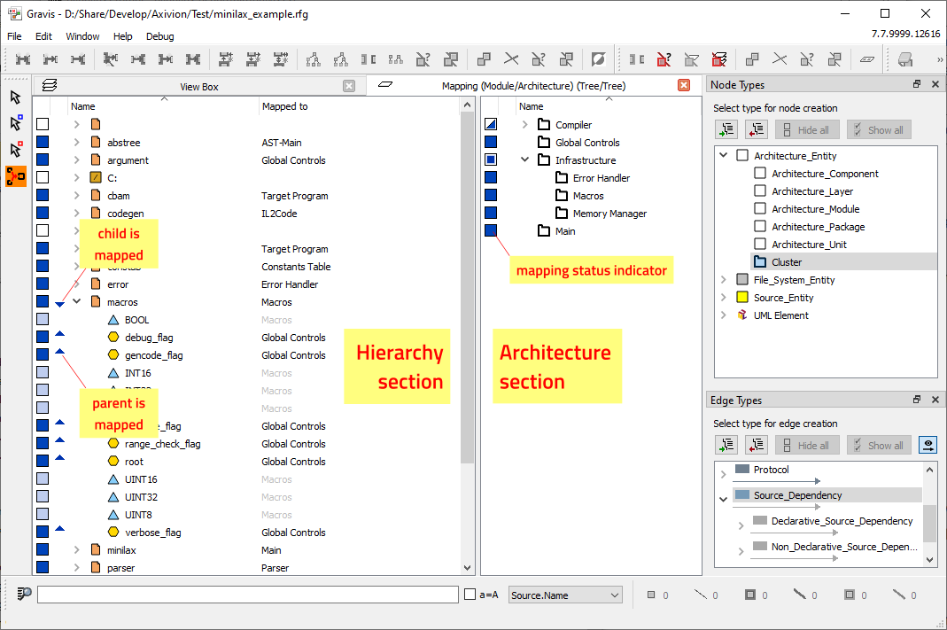
The Mapping Window with the architecture shown as a tree.
The node symbols in both sections are decorated with blue and white icons indicating each node’s mapping state.
Icon |
Hierarchy section |
Architecture section |
|---|---|---|
|
lacks a mapping |
lacks a mapping |
|
source of a mapping |
target of a mapping |
|
itself not mapped but all children are mapped |
itself not mapped to but all children are mapped to |
|
itself not mapped but some children are mapped |
itself not mapped to but some children are mapped to |
|
implicitly mapped by ancestor node |
ancestor node is mapped to |
|
implicitly mapped by ancestor node and some children are mapped |
ancestor node and some children are mapped to |


In addition, any node that is directly mapped (or mapped to) has a small arrow icon
pointing downwards ( ) if there are descendant nodes in its subtree
with a mapping that overrides this node’s mapping. You can use
) if there are descendant nodes in its subtree
with a mapping that overrides this node’s mapping. You can use Mapping → 
Select mapped
descendants
from the context menu to find them (see next section). A small arrow
pointing upwards ( ) is shown if there is an ancestor node whose
mapping is overridden by the node’s mapping.
) is shown if there is an ancestor node whose
mapping is overridden by the node’s mapping.
Mapping Window context menus
The context menus in the two sections resemble the context menus of tree or graph
windows respectively. In addition, the context menus contain a
Mapping submenu with the following operations:

Select mapped nodes selects the mapped
node (or nodes) on the other side from/to which the clicked node is mapped. The
selection in that view is cleared beforehand.
Select mapped descendants selects all
nodes in the subtree of the clicked node that are directly mapped to/from a node on the
other side. The selection is cleared beforehand and the hierarchy is expanded to reveal
the selected nodes. The main use of this operation is to find the descendants with a
more specific mapping if the small arrow icon () next to a mapped
node indicates that there are mapped nodes in its subtree.

Unmap node (flat) removes the mapping for the clicked node.

Unmap node (deep) removes the mapping for the clicked node
and its children recursively.

Unmap selection (flat) removes the mapping for all
selected nodes.

Unmap selection (deep) removes the mapping for
all selected nodes and their children recursively.
The Mapping Tool
The hierarchy and architecture sections are tree or graph windows in their own right, so
you can use the full range of tools to navigate or even edit both views. However, the
most important tool to use is the 
Mapping Tool, which is
only available in the Mapping window, and which allows you to inspect and change the
mapping from nodes in the hierarchy view to nodes in the architecture view.
The Mapping Tool works like the Select Tool in that it
allows you to select, expand and collapse nodes (and even move them around and resize
them in a graph window). What makes it different is that it allows you to drag a node or
a selection of nodes from the left section of the mapping window (the hierarchy) onto a
node in the right section (the architecture) to map the dragged node(s) to the target of
the drag.
If you drag an unselected node, just that node is mapped to the target of the drag. If
you drag a selected node, the whole selection is mapped, i. e. all other selected nodes
are mapped as well. While dragging a selection of multiple nodes, the cursor changes to
 to indicate this, as opposed to
 when dragging a single node. The curved arrow in the cursor
turns green while it points at a valid target node in the architecture section (
when dragging a single node. The curved arrow in the cursor
turns green while it points at a valid target node in the architecture section (
 when dragging a single node or
 when dragging a selection), and the target node is
highlighted.
when dragging a selection), and the target node is
highlighted.
Reviewing the mapping
The “Mapped to” column in the hierarchy section displays the mapping target of each node. A node has an explicit mapping target (shown in black) if the node itself is mapped. Children of mapped nodes that are not themselves mapped, are implicitly mapped to the same target as their parents. Implicit mappings are shown in gray.
When you click on a node in the hierarchy section that already has a mapping, then the target node of the mapping is highlighted in the architecture with a flashing purple frame (graph) or a flashing yellow background (tree). If the target node is not visible, because it is inside a collapsed parent or ancestor node, then the closest visible ancestor node is highlighted instead, but less prominently to indicate that the mapped node is inside it. In a graph, flashing purple corners are shown around the target node, and in a tree, the target node is shown with a flashing pale yellow background.
Similarly, when you click on a node in the architecture section, all nodes in the hierarchy section that are mapped to this node are highlighted in yellow (or pale yellow, if the mapped node itself is not visible).
5.9.6.2. Fixing Mapping Problems
When trying to open the mapping dialog or run architecture analysis Gravis checks the validity of the mapping view before proceeding. If there are any problems, Gravis displays an alert showing the number of problems that were found:
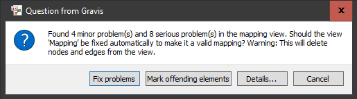
The Mapping Problems alert.
Clicking on Fix problems fixes the problems by deleting the offending
elements. This is not always the most appropriate solution, so it is recommended to
investigate the problems first via Mark offending elements first. This
marks all the nodes and edges in the mapping view that cause problems and opens the
mapping view as a flat diagram to show them. A more detailed summary can be obtained by
clicking on Details... to open the Mapping Problems Details
dialog:
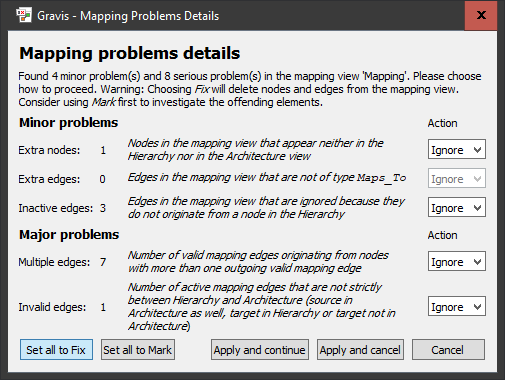
The Mapping Problems Details dialog.
This dialog shows all the details of the mapping problems and allows them to be
investigated or fixed individually by selecting the desired resolution in the
Action column on the right. The default action is to ignore the problem.
Please note that you cannot go on with your original task (opening the mapping dialog or
running architecture analysis) while there are still unresolved major problems. The
entries Fix and Mark correspond to the buttons in the
previous dialog and the same caveats apply to choosing Fix.
After setting up the actions, click on Apply and cancel to apply the
actions and review the results or Apply and continue to apply the actions
and continue with the original task (opening the mapping dialog or running architecture
analysis).
5.9.6.3. Performing Architecture Analysis
The Analysis dialog is opened by choosing
Edit → 
Run Analysis... from the main
menu to open the Analysis dialog and selecting Architecture
Checking/Perform Check in the tree display of available analyses.
The architecture analysis offers the following parameters:
The views used as
Architecture view,Mapping view,Hierarchy viewandBase view. The views with theArchitecture,Mapping, Hierarchy andBase roles assigned in the View Boxare taken as default.If the hierarchy and the relationships to be checked are both present in a single view, both
Hierarchy viewandBase viewmust be set to that view.The
Type hierarchyparameter defines the root of the edge type hierarchy to be checked. The selected type and all its subtypes are checked. The edge types that are used to model the dependencies in the architecture view have to be compatible with those representing the relationships in the base view.Note
For UML users: That is the reason why UML edges from an imported UML architecture model have to be interpreted and transformed into source dependency edges.
The
Declaration forwardingoption enables special logic for resolving declaration mapping targets. If enabled, then the root of the edge type hierarchy for which this is enabled can be set up. This mechanism is explained in the section “Handling C/C++-Declarations” in the Architecture Guide Architecture.Allow dependencies to parents: If enabled, then all relationships between elements that are mapped to a child component in the architecture and elements that are mapped to its parent or ancestor are allowed, without having to add an explicit dependency edge between the child and the parent in the architecture.Result view: The name for the result view that captures the results of running the analysis.The remaining checkboxes influence how the result view is structured and opened:
Add violating edges: Add the edges from the Base view that caused violations (
Absenceand
Divergenceedges) to the result view. This will later allow Absenceand
Divergenceedges to be double-clicked in the result view to display the list of Base view edges that caused them.Add conforming edges: Add the edges from the Base view that caused conformances (
Convergence) to the result view. This will later allow Convergenceedges to be double-clicked in the result view to display the list of Base view edges that caused them. Please note that this increases processing time and memory requirements, because a large amount of extra information has to be stored. The number of edges that conform to the architecture is typically much higher than the number of edges that violate it, so it is recommended to leave this option disabled unless the ability to check conformances is really needed.Add all nodes from hierarchy: If enabled, then all nodes from the Hierarchy view that are mapped to an architecture component are added as children of that component, else only the nodes from the Hierarchy view that are endpoints of architecture check result edges (and their ancestors) are added to the result view. Leaving this option disabled minimizes the number of source-related graph elements in the result view by excluding elements that are not responsible for any architecture check result edges.Lift architecture check result edges: If enabled, the Absence, Divergence, and Convergenceedges are lifted in the result view, i. e. additional summary edges are created between all enclosing ancestor nodes, up to the top level. This option should usually be enabled, because it makes it much easier to find result edges that are buried deep in the hierarchical structure of the architecture.Lift violating/conforming edges: If enabled, the edges from the Base view that caused architecture check result edges are lifted in the result view.Open result list: If selected, a window showing the architecture check result edges as a table is opened (similar to the way the dashboard displays the list of issues found in the analyzed system).Open graphical result view: If selected, a hierarchical graph window showing the architecture check results is opened.
The Run analysis button runs the analysis. A result view is created and
the requested result windows are opened after the analysis has finished.
If not opened automatically, the result list can be opened manually using the menu
entries

Open → Violations...,

Open → Conformances...,
or 
Open → Result edges...
from the context menu over the result view in the View Box,
depending on what kinds of result edges were computed by the analysis (violations only,
conformances only, or both).
If not opened automatically, the architecture check result view can be opened manually
by double-clicking its entry in the View Box.
5.9.6.4. Interpreting the Result of Architecture Analysis
There are two ways to view the results of Architecture Analysis:
As a Violations/Conformances/Result Edges List, which shows architecture check result edges (
Absence,
Divergenceand/or Convergence) next to their causing edges in a table display. Each architecture check result edge is caused by one or more source-related edges. In case there are multiple causing edges for a given result edge, the result edge appears several times in the table.As a graphical representation of the generated Architecture Check view, which shows the Architecture view enhanced with architecture check result edges and a browsable mapping as a graph window (see Section Graphical Windows).
The Violations List
The Violations/Conformances/Result Edges List window shows the following columns (described for violations here, the other kinds are analogous):
Column |
Contents |
|---|---|
Violation kind |
Shows if the result edge is an |
Violation source / Violation target |
The source and target node of the violation in the |
Causing edge count |
Count of edges on source level that are leading to the same violation. |
Parent of source |
Node containing the source node of the violation. The node is contained in the |
Causing source |
Source node of the violation. |
Causing edge |
Type of the edge from the Base view that causes the violation. |
Parent of target |
Node containing the target node of the violation. |
Causing target |
Target node of the violation. If the edge is a summary, the target node contains the real targets of the edges on deeper level. |
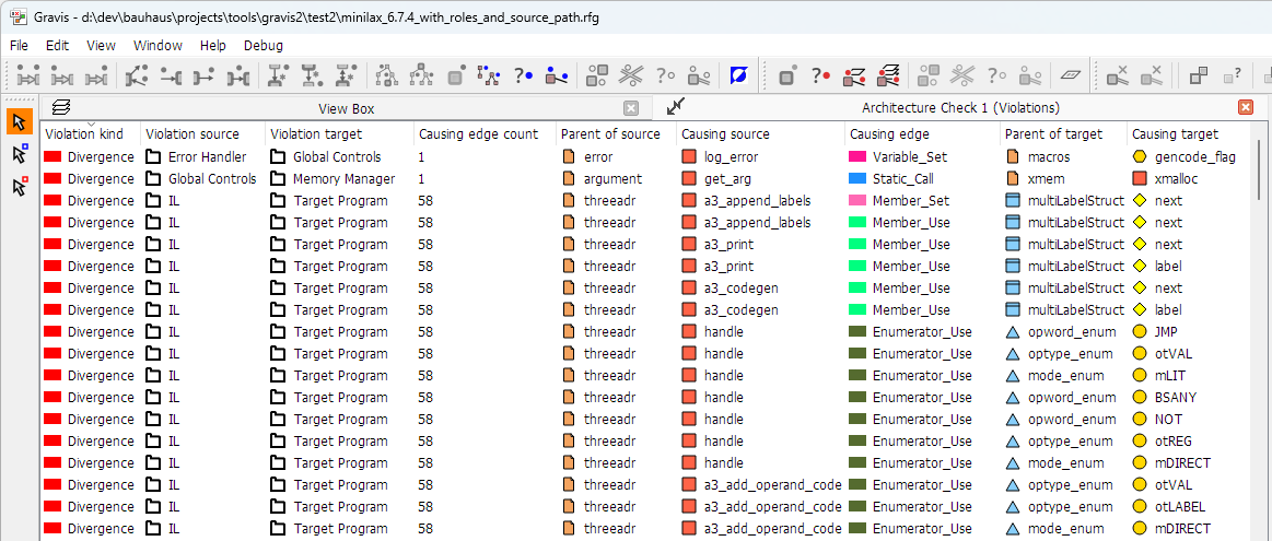
The Violations List
The first two entries in the Violations List shown above are divergences that are caused
by a single causing edge, the first one by a 
Variable_Set edge and the second one by a 
Static_Call edge. The following causing edges starting from the

Member_Set edge, followed by a 
Member_Use edge followed by many 
Enumerator_Use edges all contribute to a single Divergence from 
IL to Target_Program, which is caused by a total of 58 causing edges as indicated in the
Causing edge count column.
Although the Violations List displays nodes, it is fundamentally a list of edges – each
row represents a causing edge. Consequently, when you click on any list entry using the

Select Tool or 
Mark Tool,
the causing edge is always selected or marked, regardless of which column you click in.
Similarly, the selection or marking status is displayed only for the causing edge, and
only in the five rightmost columns, which correspond to the causing edge.
Caution
The view with which the Violations List is associated is the Architecture Check result view, not the base view. Therefore, selecting a causing edge in the Violations List will not cause it to be shown selected in a graph window showing the base view. You can use marking rather than selection to locate causing edges or their endpoints in a graph window showing the base view. The context menu offers some useful ways of marking causing edges and their endpoints.
A long list can be reduced in two ways. The Edge Types window applies to
the list as to any graph window: a row is shown only if both its violation kind and the
type of its causing edge are selected there. In addition, every column can be filtered
individually. Click the filter icon in the column header to set the column’s filter. The
header icon indicates whether a filter is active for the column, and the filters of
several columns are combined.
For all columns except Causing edge count, the filter is a text pattern.
Enter it and press Return. A row is shown only if the text in that column
contains the pattern; the comparison ignores case, * matches any sequence of
characters, and ? matches any single character. An empty pattern removes
the filter.
The Causing edge count column is filtered by a range instead. In the
min field, enter the smallest count to show, and in the
max field, the largest. Raising the minimum past the maximum carries the
maximum along. Select Unlimited if you do not want to set an upper limit.
The dialog starts out with a minimum of 0 and Unlimited selected, which
applies no filter; use Reset to return to that state. Absence entries have
no causing edge count, and an empty count is treated as 0.
The two columns that show edge types, Violation kind and
Causing edge, take part in both kinds of filtering. Use the
Edge Types window to select whole subtrees of the type hierarchy, and a
column filter to match the type name as displayed.
The Violations List context menu
The context menu over a Violations List entry consists of two parts: An optional top part that is only included if you clicked over a column showing a node, and a common part that is always present because it refers to the causing edge that is represented by the entry. It offers operations to mark the elements that are involved with this particular violation.
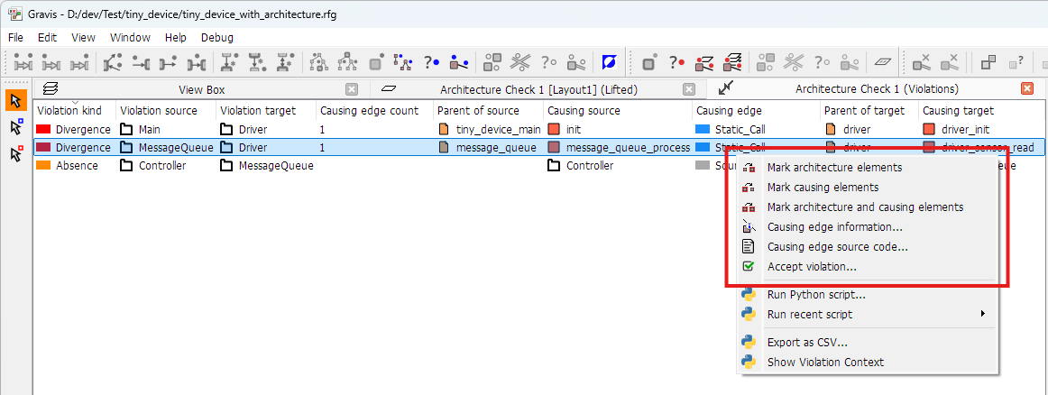
The common part of the Violations List context menu

Mark architecture elements
marks the violation edge and its endpoints in the architecture.

Mark causing elements marks the causing edge and its
endpoints in the base view.

Mark architecture and causing
elements
marks both at the same time.

Causing edge information... opens the Edge Information
windows for the causing edge.

Causing edge source code... opens Source Code
windows for the causing edge.

Accept violation... opens a dialog that helps adapting the
architecture to fix the clicked violation. See Accepting
violations for details on this dialog.
When clicking over a column showing a node, the top part of the context menu allows the
Node Information and Source Code windows for that node to be
opened and the node to be marked.
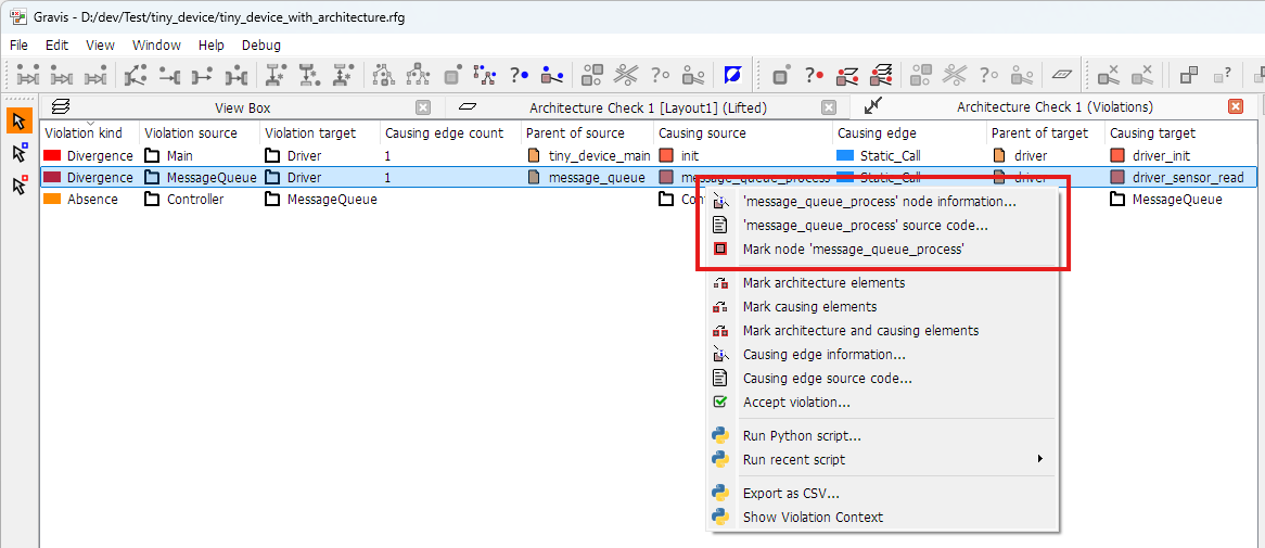
The node-specific top part of the context menu
Hint
Hovering the mouse pointer over an architecture node entry in the Violation Source or Target column shows the full hierarchical path of the node in a tooltip window.
The graphical Architecture Check result view
The result view consists of the architecture view enhanced with architecture check result edges and a browsable mapping, i. e., each architecture component contains the source code elements that were mapped to it as children.
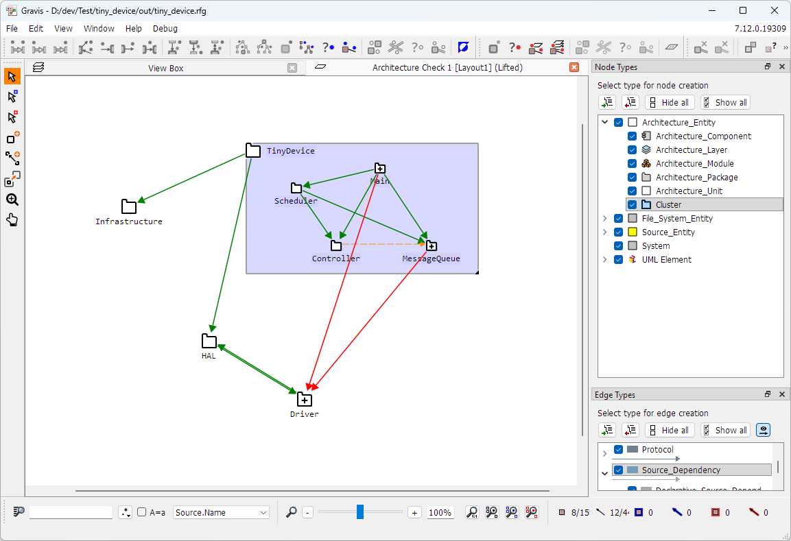
The Architecture Check result view
This arrangement allows navigating from a Divergence
summary edge all the way down to its causing edge(s) by drilling down the hierarchy,
i. e., by repeatedly expanding the nodes at both ends of the edge until the
actual source code edges are revealed that cause the divergence. This is only possible
if both the result edges and the causing edges are lifted in the result view, see the
architecture analysis options Lift architecture check result edges and
Lift violating/conforming edges in section Performing Architecture
Analysis).
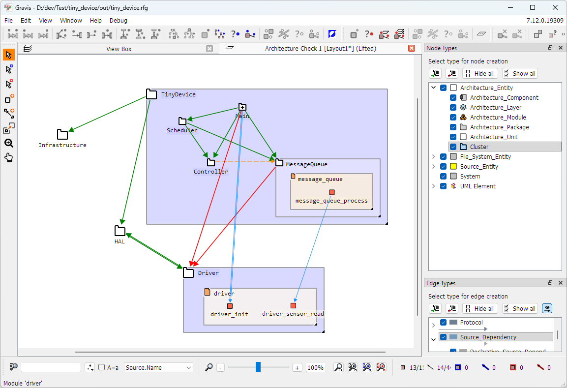
The Architecture Check result view after drilling down to one of the causing edges
In the figure above, the causing edge of the Divergence from MessageQueue to
Driver has been revealed to be a Static_Call edge from message_queue_process
to driver_sensor_read. The edge from Main to driver_init is still a
summary edge. Further expansion of Main is required to reveal its causing edge.
Double-clicking on architecture check result edges
If the Add violating edges option was enabled, then double-clicking on a
Divergence edge opens a Violation List window displaying
all source code edges that caused this violation. If the
Divergence is a summary edge, the list contains the causing edges of all
actual violations represented by the summary edge. Similarly, if the Add
conforming edges option was enabled, then double-clicking on a
Convergence edge opens a Conformances List window displaying all source
code edges that caused this conformance. If the
Convergence is a summary edge, the list contains the causing edges of all
actual conformances represented by the summary edge.
The Result view context menu
The Accept violation... entry on the context menu opens a
dialog that helps adapting the architecture to fix the clicked violation. This entry is
only available if the context menu was opened over a
Divergence or Absence edge.
Note
This entry is not available when opening the context menu over a summary edge. In order to use it you need to drill down until the actual violation edgse are revealed.
Accepting Violations
A violation in the architecture analysis results can mean one of two things:
The architecture model is correct and there is an unwanted or missing dependency in the source code (unwanted in case of a divergence or missing in case of an absence). The only way to fix this is to adapt the source code and then re-run the architecture analysis on the changed code.
The source code is correct and instead there is a missing or superfluous dependency in the architecture model (missing in case of a divergence or superfluous in case of an absence).
If the latter is the case, then the dialog opened via the menu entry
Accept violation... offers an easy way to adapt the architecture model in
order to fix the violation.
Caution
Using this facility updates the architecture view in the currently loaded RFG. Of course, this change can be saved by saving the RFG, but in a typical CI workflow the RFG is only a transient end product of the analysis. During each analysis run, the RFG is created from scratch and the architecture is typically imported from a GXL file. In order to use the updated architecture for the next CI analysis run the updated architecture view needs to be exported as a GXL file that can replace the CI architecture input file.
Accepting a Divergence
A divergence can be fixed by adding a suitable dependency to the architecture model. In
theory it would be enough to add an edge of the closest common supertype of all causing
edges that contribute to the divergence, but if the architecture model uses a more
general type throughout, e. g., 
Source_Dependency, then it is usually better to use that type for better
consistency.
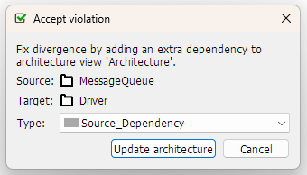
The dialog to accept a divergence
The dropdown menu of the Type combo box offers all possible edge types
that would fix the divergence. The default is the most general type, typically
Source_Dependency. Clicking on
Update architecture adds an edge of the given type to the architecture
view.
Accepting an Absence
An absence can be fixed by either removing the unmatched dependency from the architecture or keeping it and making it optional. The latter fixes the absence violation while still allowing future revisions of the software to make use of the dependency.
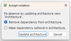
The dialog to accept an absence
The dialog offers both possible fixes. Clicking on Update architecture
performs the selected action.