
5.9.8. Menu Reference
This reference section describes all Gravis menu entries. In this section, the
terms clicked node, clicked edge and clicked element (and in the View
Box also clicked view) refer to the object the mouse is over when the context menu is
opened. The term current view is the view shown in the active graph window.
If a menu entry can be bound to a keyboard shortcut its operation name appears next to it in its description below. This name can be used to change or assign a keyboard shortcut, see Keyboard shortcuts for details.
5.9.8.1. Main Menu
Edit menu
- Run analysis…
Edit.RunAnalysis Opens the analysis window from which an analysis to be executed can be selected.
- Architectural mapping
Opens a mapping window (see Section Mapping Window) using the currently assigned roles. The
 Hierarchy view is always shown as
a tree. The
Hierarchy view is always shown as
a tree. The  Architecture view can be represented as a graph
or as a tree:
Architecture view can be represented as a graph
or as a tree:- Architecture as tree…
Edit.Mapping.ArchitectureAsTree The
Architecture view is shown as a tree.- Architecture as graph…
Edit.Mapping.ArchitectureAsGraph The
Architecture view is shown as a graph.
- Architecture as tree…
- Architecture pipeline…
Edit.ArchitecturePipeline Opens the Pipeline Setup dialog. It allows loading an architecture pipeline configuration file in order to view and execute the pipeline in Gravis. See Architecture Pipeline Execution.
- Recent pipelines
Shows a list of the most recently opened pipeline configurations for easy access.
Window
- Reset “don’t show again” dialogs
Window.ResetDontShowAgainDialogs Makes Gravis forget about all choices made for “don’t show again” checkboxes in dialogs, allowing all dialogs to be shown again.
- Tabs position
Changes the position of the tabs in the central tabbed area (top, bottom, left or right).
- Persistent palette visibilities
If ticked, the visibility states of the palette windows (as indicated in the palettes section below this menu entry) are preserved across sessions, which allows switching off individual toolbars permanently for the current user.
The final two sections in the menu are the palettes section and the windows section.
The palettes section lists all dockable palette windows and allows each of them to be shown or hidden. These are:
- Node Types
Shows the node types hierarchy.
- Edge Types
Shows the edge types hierarchy.
- Toolbox
Shows the available tools.
- Quick Finder/Zoom/Statistics
Toolbar with the Quick Finder, the Zoom Bar with quick access icons for entries from the
Zoommenu, and the Statistics Bar.- Selection Toolbar
Quick access toolbar for entries from the
Selectmenu.- Marking Toolbar
Quick access toolbar for entries from the
Markmenu.- Edit/Hide/Show Toolbar
Quick access toolbar for entries from the
EditandHide and Showmenus.
The windows section lists all opened windows for quick reference. Choosing a window entry activates the window.
Help
- About
Help.About Shows version information about Gravis.
- User manual
Help.UserManual Opens the Gravis user manual in a web browser.
5.9.9. Customizing Gravis
Many aspects of the way in which Gravis operates can be adapted and enhanced via the
Gravis configuration. You can find the Gravis rule with various options in the
Tools aspect in the graphical configuration interface.
Note
Configuration changes only come into effect after quitting and restarting Gravis.
5.9.9.1. Visualization options
The way Gravis displays graphical diagrams is controlled by the graph_style
option in the Gravis rule. For instance, you can set the background color of graph
windows (default: white) via the option graph_style.background_color.
By default, node and edge labels are shown in black, but this can be changed
via the option graph_style.default_label_color. You can define
the colors and shapes of nodes via graph_style.node_types
and the color, thickness, dash pattern and arrow types/sizes of edges via
graph_style.edge_types. Both are dictionaries that map node/edge type names
to a hierarchy of structured settings. You can leave any of the child settings at
None (unspecified), which makes the given type inherit this property from its
parent in the type hierarchy as shown in the Gravis Node/Edge Type panels.
By default, most settings of most types are None (unspecified). That allows
you to set properties for whole subtrees of the type hierarchy. For instance, if you
set Source_Dependency.width to 2.0 in graph_style.edge_types, then
all edge types in the subtree of Source_Dependency, e.g., Static_Call
and Variable_Use are shown 2 pixels wide. You can still override the width
of individual types by setting a specific value there.
Custom Node and Edge Types
The graph_style.node_types and graph_style.edge_types dictionaries
contain entries for all predefined node and edge types. In addition to editing these
entries, you can add new entries for any custom node and edge types you want to use
by clicking on the New entry... button in the node/edge_types
edit dialog and entering the name of your custom type. After restarting Gravis, if a
loaded graph contains a node/edge type of the given name or a type of that name is created
in the graph, the settings of this entry are used to visualize it.
If a graph contains node/edge types that are not mentioned in the
graph_style.node/edge_types dictionaries, their visualization settings are
inherited from their parents in the type hierarchy and the __default__ entry as the
implicit parent of all top-level types.
Adding SVG Icons
Gravis defines a set of predefined node shapes. In addition, you can use any SVG
graphic as a node shape for existing node types or custom node types. The shapes
sub-option of the entries in the graph_style.node_types dictionary accept either
the name of a predefined node shape or the filename of an SVG file (as an absolute path
or relative to the directory containing the configuration file).
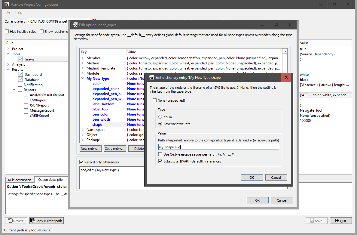
Using the graphical configuration interface to configure a custom node type to use an SVG icon.
The size and position of the icon in the SVG file is not important. Gravis scales it to make its size match that of the predefined node shapes.
Adding custom icons without configuration changes (legacy mechanism)
Gravis has a legacy mechanism to look for custom icons for node types that have no
shape configuration in node_types, either because they do not appear in
the dictionary or because their shape option is set to None. It looks
for files with a .svg extension in the directory custom_icons inside any
configuration layer, i. e., inside any directory listed in
BAUHAUS_CONFIG or inside the directory .bauhaus in the user’s home
directory. The found files are associated with node types using their names, so the file
$(HOME)/.bauhaus/custom_icons/MyType.svg is used for nodes of type
MyType (and its subtypes in the type hierarchy as long as they have no
explicit shape configuration). This mechanism is deprecated and may be removed
in a future version of Gravis.
Node and Edge Labels
Gravis can show labels at the top and bottom of nodes and at six different
positions around edges: at the top and bottom near the source node, at the top
and bottom in the middle of the edge, and at the top and bottom near the target
node. For each node/edge type, each of these two/six positions can show nothing,
a fixed string or a string that depends on the presence and contents of an
attribute. For instance, the option label_top in the Routine entry
of graph_style.node_types controls which label is shown at the top of
Routine nodes (or any sub-types of Routine, for which this key is not
explicitly overridden). The option label_middle_top in the UML Relation
entry in graph_style.edge_types controls which label is shown above
UML Relation edges in the middle between the start and the end node.
The value of these label options is a label specification, which is either just the key of an attribute to display or a list of comma-separated key=value pairs that define various aspects of the label, including its display style. Comma and backslash characters in a value must be quoted with a backslash character. Available label specification keys are:
attr=nameSpecifies the key of an attribute to display. If the attribute is not present, the default is shown, if the key
defaultis specified, else no label is shown. For attributes other than boolean flags, the attribute value is shown, optionally, betweenprefixandsuffixif these keys are specified. If the attribute is a boolean flag, the redundant valuetrueis never shown, but instead onlyprefixis shown, which must be specified in this case, else nothing is shown at all.bold=flagSpecifies whether the label should be shown in a bold font.
default=stringSpecifies a string to be shown if the specified attribute is not set. If no
attrkey is specified, the default string is always shown.italic=flagSpecifies whether the label should be shown in an italic font.
size=+/-numberSpecifies the relative font size to be used. A positive value makes the label appear larger than the default label font size, a negative values makes it appear smaller. The increment/decrement is measured in points.
prefix=stringSpecifies a string to be shown before the attribute value. Only shown if the attribute is set. Optional, except when
attrrefers to a boolean flag attribute, in which case this key is required.suffix=stringSpecifies a string to be shown after the attribute value. Only shown if the attribute is set. Not shown for boolean flag attributes.
Either attr or default must be present for a label setting
to have any effect at all.
Example label specifications:
attr=UML.Stereotypes,bold=true,size=-1shows the contents of the attribute
UML.Stereotypesin a bold font and 1pt smaller than the normal label font size, or nothing if the attribute is not set.attr=Metric.Lines.LOC,prefix=LOC=,default=(no LOC)shows the contents of the integer attribute
Metric.Lines.LOCprefixed byLOC=, or(no LOC)if the attribute is not set.default=Association,italic=trueshows the label
Associationin an italic font unconditionally for each node/edge type for which this label is configured.attr=Element.Is_Optional,prefix=optionalshows
optionalifElement.Is_Optionalis set, else nothing.attr=Element.Is_Optional,prefix=optional,default=mandatoryshows
optionalifElement.Is_Optionalis set, elsemandatory.
Variable edge widths
Gravis can be configured to show different edge widths depending on applied attribute values. For instance, this can be used to show thicker edges for architecture violations that are caused by many unwanted source code dependencies.
To enable this feature for an edge type, set up the width_multiplier field in
its entry in the graph_style.edge_types dictionary. This field is set to a
multiplier specification, which is a semicolon-separated sequence of multiplier
expressions. The first applicable multiplier expression computes the multiplier,
i.e., the value by which the configured width of the given edge is multiplied.
Expressions that do not have the expected format or mention an attribute that is not
applied to the edge are skipped. If all expressions are skipped, the edge width remains
unchanged. The sequencing allows the multiplier to be computed based on several
attributes with a priority ordering.
A multiplier expression has the format func(param1, param2, ..., paramN), where
each parameter is either a float value or the name of a numeric attribute (i.e., an
attribute of int or float type).
Currently, the only available function is map_range(attr_name, vmin, vmax,
rmin, rmax), which looks up the attribute attr_name and maps attribute values
between vmin and vmax to the result range rmin to rmax.
Attribute values below vmin are mapped to rmin and attribute values
larger than vmax are mapped to rmax.
Example multiplier expression:
Architecture analysis result edges (i.e., 
Divergence and

Convergence edges) have an integer attribute
Analysis.Causing_Edge_Count that specifies the number of source code
dependencies that contributed to this result edge.
If you set the following width_multiplier for the
Architecture_Check_Result edge type:
map_range(Analysis.Causing_Edge_Count,1,21,1.0,6.0)
then result edges caused by 1 source code dependency are shown at the original edge width, whereas edges caused by 21 or more source code dependencies are shown at 6 times the configured edge width. An edge caused by 5 source code dependencies (20% along the way from 1 to 21) would be shown at 2.0 times the configured width (also 20% along the way from 1.0 to 6.0).
To only show divergence edges with different widths, apply this setting to the
Divergence edge type instead of its supertype
Architecture_Check_Result.
5.9.9.2. Keyboard shortcuts
Gravis offers keyboard shortcuts for many menu entries. If there is a shortcut for a menu entry it is shown next to it. It is possible to change the existing shortcuts and to assign shortcuts to most of the menu operations that do not yet offer a shortcut.
To add or change keyboard shortcuts add a file named gravis_shortcuts.txt to any
configuration layer, i. e., either a directory listed in
BAUHAUS_CONFIG or the directory .bauhaus in the user’s home
directory. If there is more than one such file standard layering rules apply, so changes
made in more local layers override those made in more global layers. The
.bauhaus directory in the user’s home directory is considered the most local
layer.
The gravis_shortcuts.txt file associates operation names with keyboard
shortcuts, e. g.:
# my personal shortcuts
Graph.LayoutStorage.SaveAsPNG      Ctrl+F2
Graph.LayoutStorage.SaveAsPDF      Ctrl+F3     # next to "SaveAsPNG" on the keyboard
Diagram.Edit.DeleteSelection       # clear shortcut to avoid accidents
You can find the operation names in the menu reference section above.
Use any number of whitespace characters to separate the operation name from the shortcut. Shortcut are specified using English key names (Ctrl, Shift, etc.) independent of the computer’s locale settings. Leaving out the shortcut definition clears any existing shortcut for the given operation. Comments are introduced by a hash character and extend to the end of the current line.
If the same operation occurs more than once in a file the last change in the file wins.
The command clear on its own on a line clears all shortcuts assigned so far,
allowing you to start setting up all shortcuts from from scratch. That can be useful to
avoid conflicts between newly assigned shortcuts and predefined shortcuts.
Conditional blocks
It is possible to define platform-specific shortcuts using
ifeq/else/endif constructs similar to GNU make:
ifeq ($(PLATFORM),Windows)
   File.Reload                            F5
else
   File.Reload                            Ctrl+R
endif
The else branch is optional. Use ifneq instead to test for inequality.
Conditional constructs can be nested.
$(PLATFORM) is a pseudo-variable that resolves to Windows,
Linux or macOS depending on the current platform. Any other variable
name is looked up as an environment variable. A non-existing environment variable
expands to the empty string.
Conflict resolution
Each operation can only have a single shortcut, and each possible shortcut can only be assigned to a single operation. The first requirement is always satisfied: As described above later changes override earlier ones, so if the same operation appears more than once in a shortcuts file, the last change in the most local layer wins.
A similar logic is also true for shortcuts appearing more than once on the right hand side: If a shortcut that was already mentioned before is assigned to a different operation the association with the earlier operation is removed. Again, the last use in the most local layer wins. These conflicts are not very obvious so they result in a warning.
Conflict resolution also takes menu scripts into account that are bound to keyboard shortcuts (see Adding Scripts to Menus, Shortcuts and Events). Menu scripts are considered more local than shortcuts files, so if the same shortcut is assigned in a shortcuts file and in a menu script, the menu script wins, no matter in which layers the definitions are. This kind of conflict also results in a warning.
Additional operations
In addition to the operation names shown next to menu entries in this chapter there are the following non-menu operations that can be bound to keyboard shortcuts:
Diagram.RenameNodeto rename the node under the pointer (default: F2)Tools.Navigate(default: F3),Tools.Select(default: F4),Tools.Mark(default: F5),Tools.Node(default: F6),Tools.Edge(default: F7),Tools.Hierarchy(default: F8),Tools.Zoom(default: F9),Tools.Scroll(default: F10),Tools.Mapping(default: F11) to select a toolVisualization.ToggleEdgeBundlingto toggle the edge bundling visualization option (default: Ctrl+Shift+B)
5.9.10. Command-line parameters
Usage:
gravis [options] <input file(s)>
There can be at most one RFG input file (extension .rfg) and any number of GXL
input files (extension .gxl). The RFG file, if specified, is loaded first, then
the GXL files are imported into the loaded RFG. If no RFG file is specified but one or
more GXL files, then the GXL files are imported into an empty RFG.
Options:
--script <script filename>Runs the given Python script at startup (after loading input files).
--script-param <parameter>Adds a parameter to be passed to the Python script (only useful in conjunction with
--script).--noscriptDisable Python scripting.
--quitCauses Gravis to quit after startup (mainly useful in conjunction with
--script), enables non-interactive mode.--font <font name>Specifies the font to be used in the user interface.
--font-size <font size>Specifies the font size in pt to be used in the user interface (in conjunction with
--font). 0 for system default.--ignore_geometryPrevents window position and size information stored during the previous session from being loaded. Useful if the information has become corrupted and causes the window to be opened off-screen.
--basepath <path>Specifies the base path used for source code lookup.
--no_platform_overrideDo not override the platform to
offscreenfor non-interactive Linux/macOS use.--no_translatePrevents translation files from being loaded and forces the English UI to be shown.
--translate <locale>Overrides the system locale for finding translation files. If this option is not specified, the locale name is read from the environment variable
AXIVION_UI_LANGUAGE, and if that variable is not set, the system locale is used to determine the preferred UI language.
In addition to these options, the common options of Axivion Suite tools are supported (see Tool Reference).