
基本的な描画の例
「基本的な描画」の例では、QPainter クラスを使用して、基本的なグラフィックプリミティブをさまざまなスタイルで表示する方法を示します。
QPainter は、ウィジェットやその他の描画デバイスに対して低レベルの描画処理を行います。このクラスでは、単純な線から円や弦のような複雑な形状まで、あらゆるものを描画できます。また、整列したテキストやピクマップの描画も可能です。通常は「自然な」座標系で描画しますが、ビュー変換やワールド変換を行うこともできます。
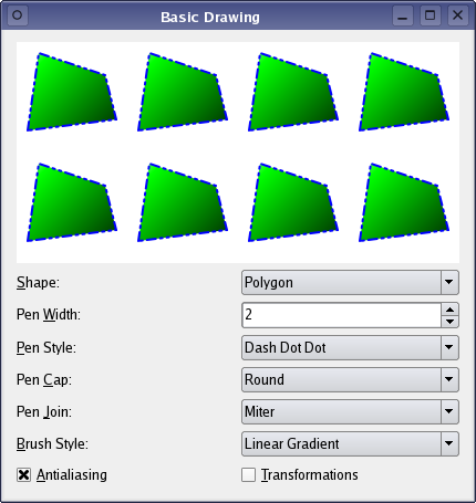
この例では、現在アクティブな図形を表示するレンダリング領域を提供し、ユーザーがQPainter のパラメータを使用して、レンダリングされた図形とその外観を操作できるようにしています。ユーザーは、アクティブな図形を変更(Shape )したり、QPainter のペン(Pen Width 、Pen Style 、Pen Cap 、Pen Join )、ブラシ(Brush Style )、およびレンダリングヒント(Antialiasing )を変更したりできます。 さらに、ユーザーは図形を回転させることができます(Transformations )。内部的には、QPainter の座標系を操作する機能を利用して回転を実行しています。
「Basic Drawing」のサンプルは、2つのクラスで構成されています:
RenderAreaは、現在アクティブな図形の複数のコピーを描画するカスタムウィジェットです。Windowは、RenderAreaウィジェットに加え、いくつかのパラメータウィジェットを表示するアプリケーションのメインウィンドウです。
まず、Window クラスについて確認し、次にRenderArea クラスについて見ていきます。
Windowクラスの定義
Window クラスはQWidget を継承しており、いくつかのパラメータウィジェットに加えてRenderArea ウィジェットを表示するアプリケーションのメインウィンドウです。
class Window : public QWidget
{
    Q_OBJECT

public:
    Window();

private slots:
    void shapeChanged();
    void penChanged();
    void brushChanged();

private:
    RenderArea *renderArea;
    QLabel *shapeLabel;
    QLabel *penWidthLabel;
    QLabel *penStyleLabel;
    QLabel *penCapLabel;
    QLabel *penJoinLabel;
    QLabel *brushStyleLabel;
    QLabel *otherOptionsLabel;
    QComboBox *shapeComboBox;
    QSpinBox *penWidthSpinBox;
    QComboBox *penStyleComboBox;
    QComboBox *penCapComboBox;
    QComboBox *penJoinComboBox;
    QComboBox *brushStyleComboBox;
    QCheckBox *antialiasingCheckBox;
    QCheckBox *transformationsCheckBox;
};ここでは、各種ウィジェットと、RenderArea ウィジェットを更新する3つのプライベートスロットを宣言します。shapeChanged() スロットは、ユーザーが現在アクティブな図形を変更した際に、RenderArea ウィジェットを更新します。penChanged() スロットは、QPainter のペンパラメータのいずれかが変更された際に呼び出されます。また、brushChanged() スロットは、ユーザーがペインターのブラシスタイルを変更した際に、RenderArea ウィジェットを更新します。
Windowクラスの実装
コンストラクタでは、メインアプリケーションウィンドウに表示されるさまざまなウィジェットを作成し、初期化します。
Window::Window()
{
    renderArea = new RenderArea;

    shapeComboBox = new QComboBox;
    shapeComboBox->addItem(tr("Polygon"), RenderArea::Polygon);
    shapeComboBox->addItem(tr("Rectangle"), RenderArea::Rect);
    shapeComboBox->addItem(tr("Rounded Rectangle"), RenderArea::RoundedRect);
    shapeComboBox->addItem(tr("Ellipse"), RenderArea::Ellipse);
    shapeComboBox->addItem(tr("Pie"), RenderArea::Pie);
    shapeComboBox->addItem(tr("Chord"), RenderArea::Chord);
    shapeComboBox->addItem(tr("Path"), RenderArea::Path);
    shapeComboBox->addItem(tr("Line"), RenderArea::Line);
    shapeComboBox->addItem(tr("Polyline"), RenderArea::Polyline);
    shapeComboBox->addItem(tr("Arc"), RenderArea::Arc);
    shapeComboBox->addItem(tr("Points"), RenderArea::Points);
    shapeComboBox->addItem(tr("Text"), RenderArea::Text);
    shapeComboBox->addItem(tr("Pixmap"), RenderArea::Pixmap);

    shapeLabel = new QLabel(tr("&Shape:"));
shapeLabel->setBuddy(shapeComboBox);まず、現在アクティブな図形を描画するRenderArea ウィジェットを作成します。次に、Shape コンボボックスを作成し、関連する項目(つまり、QPainter が描画できるさまざまな図形)を追加します。
    penWidthSpinBox = new QSpinBox;
    penWidthSpinBox->setRange(0, 20);
    penWidthSpinBox->setSpecialValueText(tr("0 (cosmetic pen)"));

    penWidthLabel = new QLabel(tr("Pen &Width:"));
penWidthLabel->setBuddy(penWidthSpinBox);QPainterペンは `QPen ` オブジェクトです。QPen クラスは、ペインターが線や図形の輪郭をどのように描画すべきかを定義します。ペンには、幅(Width)、スタイル(style)、キャップ(cap)、ジョイン(join)といったプロパティがあります。
ペンの幅はゼロ以上とできますが、最も一般的な幅はゼロです。なお、これは0ピクセルを意味するのではなく、数学的には正確ではないかもしれませんが、図形が可能な限り滑らかに描画されることを意味します。
Pen Width パラメータ用にQSpinBox を作成します。
    penStyleComboBox = new QComboBox;
    penStyleComboBox->addItem(tr("Solid"), static_cast<int>(Qt::SolidLine));
    penStyleComboBox->addItem(tr("Dash"), static_cast<int>(Qt::DashLine));
    penStyleComboBox->addItem(tr("Dot"), static_cast<int>(Qt::DotLine));
    penStyleComboBox->addItem(tr("Dash Dot"), static_cast<int>(Qt::DashDotLine));
    penStyleComboBox->addItem(tr("Dash Dot Dot"), static_cast<int>(Qt::DashDotDotLine));
    penStyleComboBox->addItem(tr("None"), static_cast<int>(Qt::NoPen));

    penStyleLabel = new QLabel(tr("&Pen Style:"));
    penStyleLabel->setBuddy(penStyleComboBox);

    penCapComboBox = new QComboBox;
    penCapComboBox->addItem(tr("Flat"), Qt::FlatCap);
    penCapComboBox->addItem(tr("Square"), Qt::SquareCap);
    penCapComboBox->addItem(tr("Round"), Qt::RoundCap);

    penCapLabel = new QLabel(tr("Pen &Cap:"));
    penCapLabel->setBuddy(penCapComboBox);

    penJoinComboBox = new QComboBox;
    penJoinComboBox->addItem(tr("Miter"), Qt::MiterJoin);
    penJoinComboBox->addItem(tr("Bevel"), Qt::BevelJoin);
    penJoinComboBox->addItem(tr("Round"), Qt::RoundJoin);

    penJoinLabel = new QLabel(tr("Pen &Join:"));
penJoinLabel->setBuddy(penJoinComboBox);ペンのスタイルは線の種類を定義します。デフォルトのスタイルは実線(Qt::SolidLine )です。スタイルをなし(Qt::NoPen )に設定すると、ペインターは線や輪郭線を描画しないように指示されます。ペンのキャップは、線の端点がどのように描画されるかを定義します。また、ペンのジョインは、複数の接続された線が描画された際に、2本の線がどのように接続されるかを定義します。 cap および join は、幅が 1 ピクセル以上の線にのみ適用されます。
各Pen Style 、Pen Cap 、Pen Join パラメータに対してQComboBoxを作成し、関連する項目(つまり、それぞれQt::PenStyle 、Qt::PenCapStyle 、Qt::PenJoinStyle 列挙型の値)を追加します。
    brushStyleComboBox = new QComboBox;
    brushStyleComboBox->addItem(tr("Linear Gradient"),
            static_cast<int>(Qt::LinearGradientPattern));
    brushStyleComboBox->addItem(tr("Radial Gradient"),
            static_cast<int>(Qt::RadialGradientPattern));
    brushStyleComboBox->addItem(tr("Conical Gradient"),
            static_cast<int>(Qt::ConicalGradientPattern));
    brushStyleComboBox->addItem(tr("Texture"), static_cast<int>(Qt::TexturePattern));
    brushStyleComboBox->addItem(tr("Solid"), static_cast<int>(Qt::SolidPattern));
    brushStyleComboBox->addItem(tr("Horizontal"), static_cast<int>(Qt::HorPattern));
    brushStyleComboBox->addItem(tr("Vertical"), static_cast<int>(Qt::VerPattern));
    brushStyleComboBox->addItem(tr("Cross"), static_cast<int>(Qt::CrossPattern));
    brushStyleComboBox->addItem(tr("Backward Diagonal"), static_cast<int>(Qt::BDiagPattern));
    brushStyleComboBox->addItem(tr("Forward Diagonal"), static_cast<int>(Qt::FDiagPattern));
    brushStyleComboBox->addItem(tr("Diagonal Cross"), static_cast<int>(Qt::DiagCrossPattern));
    brushStyleComboBox->addItem(tr("Dense 1"), static_cast<int>(Qt::Dense1Pattern));
    brushStyleComboBox->addItem(tr("Dense 2"), static_cast<int>(Qt::Dense2Pattern));
    brushStyleComboBox->addItem(tr("Dense 3"), static_cast<int>(Qt::Dense3Pattern));
    brushStyleComboBox->addItem(tr("Dense 4"), static_cast<int>(Qt::Dense4Pattern));
    brushStyleComboBox->addItem(tr("Dense 5"), static_cast<int>(Qt::Dense5Pattern));
    brushStyleComboBox->addItem(tr("Dense 6"), static_cast<int>(Qt::Dense6Pattern));
    brushStyleComboBox->addItem(tr("Dense 7"), static_cast<int>(Qt::Dense7Pattern));
    brushStyleComboBox->addItem(tr("None"), static_cast<int>(Qt::NoBrush));

    brushStyleLabel = new QLabel(tr("&Brush:"));
    brushStyleLabel->setBuddy(brushStyleComboBox);
QBrush クラスは、QPainter によって描画される図形の塗りつぶしパターンを定義します。デフォルトのブラシスタイルはQt::NoBrush です。このスタイルは、ペインターに対して図形を塗りつぶさないよう指示します。塗りつぶしの標準スタイルはQt::SolidPattern です。
Brush Style パラメータ用にQComboBox を作成し、関連する項目(つまり、Qt::BrushStyle 列挙型の値)を追加します。
    otherOptionsLabel = new QLabel(tr("Options:"));
antialiasingCheckBox = new QCheckBox(tr("&Antialiasing"));アンチエイリアシングは、ピクセルを「滑らかに」して、より均一でギザギザの少ない線を作成する機能であり、QPainter のレンダリングヒントを使用して適用できます。QPainter::RenderHints は、QPainter に対するフラグを指定するために使用されますが、特定のエンジンによってその指定が反映されるかどうかは保証されません。
Antialiasing オプションに対して、QCheckBox を単純に作成します。
transformationsCheckBox = new QCheckBox(tr("&Transformations"));Transformations オプションは、座標系の操作を意味し、レンダリングされた図形が 3 次元で回転しているかのように見えます。
QPainter::translate()、QPainter::rotate()、QPainter::scale() 関数を使用して、メインアプリケーションウィンドウで単純なQCheckBox によって表現されるこの機能を実装します。
    connect(shapeComboBox, &QComboBox::activated,
            this, &Window::shapeChanged);
    connect(penWidthSpinBox, &QSpinBox::valueChanged,
            this, &Window::penChanged);
    connect(penStyleComboBox, &QComboBox::activated,
            this, &Window::penChanged);
    connect(penCapComboBox, &QComboBox::activated,
            this, &Window::penChanged);
    connect(penJoinComboBox, &QComboBox::activated,
            this, &Window::penChanged);
    connect(brushStyleComboBox, &QComboBox::activated,
            this, &Window::brushChanged);
    connect(antialiasingCheckBox, &QAbstractButton::toggled,
            renderArea, &RenderArea::setAntialiased);
    connect(transformationsCheckBox, &QAbstractButton::toggled,
renderArea, &RenderArea::setTransformed);次に、静的関数QObject::connect()を使用して、パラメータウィジェットを関連するスロットに接続し、ユーザーが形状やその他のパラメータを変更するたびに、RenderArea ウィジェットが確実に更新されるようにします。
    QGridLayout *mainLayout = new QGridLayout;
    mainLayout->setColumnStretch(0, 1);
    mainLayout->setColumnStretch(3, 1);
    mainLayout->addWidget(renderArea, 0, 0, 1, 4);
    mainLayout->addWidget(shapeLabel, 2, 0, Qt::AlignRight);
    mainLayout->addWidget(shapeComboBox, 2, 1);
    mainLayout->addWidget(penWidthLabel, 3, 0, Qt::AlignRight);
    mainLayout->addWidget(penWidthSpinBox, 3, 1);
    mainLayout->addWidget(penStyleLabel, 4, 0, Qt::AlignRight);
    mainLayout->addWidget(penStyleComboBox, 4, 1);
    mainLayout->addWidget(penCapLabel, 3, 2, Qt::AlignRight);
    mainLayout->addWidget(penCapComboBox, 3, 3);
    mainLayout->addWidget(penJoinLabel, 2, 2, Qt::AlignRight);
    mainLayout->addWidget(penJoinComboBox, 2, 3);
    mainLayout->addWidget(brushStyleLabel, 4, 2, Qt::AlignRight);
    mainLayout->addWidget(brushStyleComboBox, 4, 3);
    mainLayout->addWidget(otherOptionsLabel, 5, 0, Qt::AlignRight);
    mainLayout->addWidget(antialiasingCheckBox, 5, 1, 1, 1, Qt::AlignRight);
    mainLayout->addWidget(transformationsCheckBox, 5, 2, 1, 2, Qt::AlignRight);
    setLayout(mainLayout);

    shapeChanged();
    penChanged();
    brushChanged();
    antialiasingCheckBox->setChecked(true);

    setWindowTitle(tr("Basic Drawing"));
}最後に、さまざまなウィジェットをレイアウトに追加し、shapeChanged() 、penChanged() 、brushChanged() の各スロットを呼び出してアプリケーションを初期化します。また、アンチエイリアシングを有効にします。
void Window::shapeChanged()
{
    RenderArea::Shape shape = RenderArea::Shape(shapeComboBox->itemData(
            shapeComboBox->currentIndex(), IdRole).toInt());
    renderArea->setShape(shape);
}
shapeChanged() スロットは、ユーザーが現在アクティブな図形を変更するたびに呼び出されます。
まず、QComboBox::itemData() 関数を使用して、ユーザーが選択したシェイプを取得します。この関数は、コンボボックス内の指定されたインデックスにある指定されたロールのデータを返します。QComboBox::currentIndex() を使用してシェイプのインデックスを取得し、ロールはQt::ItemDataRole 列挙型で定義されています。IdRole はQt::UserRole の別名です。
なお、Qt::UserRole は、アプリケーション固有の目的で使用できる最初のロールにすぎません。同じインデックスに異なるデータを格納する必要がある場合は、Qt::UserRole の値を単純にインクリメントすることで、異なるロールを使用できます。例えば、「Qt::UserRole + 1」や「Qt::UserRole + 2」などです。 ただし、各ロールに固有の名前を付けることは、良いプログラミングの慣習です。例えば、「'myFirstRole =Qt::UserRole + 1'」や「'mySecondRole =Qt::UserRole + 2'」といった具合です。この特定の例では 1 つのロールしか必要としませんが、window.cpp ファイルの先頭に次のコード行を追加します。
const int IdRole = Qt::UserRole;QComboBox::itemData() 関数はデータを `QVariant` として返すため、データを `RenderArea::Shape` にキャストする必要があります。指定されたロールに関するデータがない場合、この関数は `QMetaType::UnknownType` を返します。
最後に、RenderArea::setShape() スロットを呼び出して、RenderArea ウィジェットを更新します。
void Window::penChanged()
{
    int width = penWidthSpinBox->value();
    Qt::PenStyle style = Qt::PenStyle(penStyleComboBox->itemData(
            penStyleComboBox->currentIndex(), IdRole).toInt());
    Qt::PenCapStyle cap = Qt::PenCapStyle(penCapComboBox->itemData(
            penCapComboBox->currentIndex(), IdRole).toInt());
    Qt::PenJoinStyle join = Qt::PenJoinStyle(penJoinComboBox->itemData(
            penJoinComboBox->currentIndex(), IdRole).toInt());

    renderArea->setPen(QPen(Qt::blue, width, style, cap, join));
}ユーザーがペンパラメータのいずれかを変更するたびに、penChanged() スロットを呼び出します。ここでも、QComboBox::itemData()関数を使用してパラメータを取得し、その後、RenderArea::setPen() スロットを呼び出してRenderArea ウィジェットを更新します。
brushChanged()スロットは、ユーザーがブラシパラメータを変更するたびに呼び出されます。このパラメータは、前述と同様にQComboBox::itemData()関数を使用して取得します。
    if (style == Qt::LinearGradientPattern) {
        QLinearGradient linearGradient(0, 0, 100, 100);
        linearGradient.setColorAt(0.0, Qt::white);
        linearGradient.setColorAt(0.2, Qt::green);
        linearGradient.setColorAt(1.0, Qt::black);
        renderArea->setBrush(linearGradient);
brush パラメータがグラデーション塗りつぶしである場合は、特別な処理が必要になります。
グラデーション塗りつぶしを指定するには、QGradient クラスをQBrush と組み合わせて使用します。Qt は現在、線形、放射状、円錐状の 3 種類のグラデーション塗りつぶしをサポートしています。これらはそれぞれ、QGradient のサブクラスであるQLinearGradient 、QRadialGradient 、QConicalGradient によって表現されます。
したがって、ブラシスタイルがQt::LinearGradientPattern の場合、まずコンストラクタの引数として渡された座標間の補間領域を持つQLinearGradient オブジェクトを作成します。位置は論理座標を使用して指定されます。次に、QGradient::setColorAt()関数を使用してグラデーションの色を設定します。 色は、位置(0から1の間)とQColor で構成されるストップポイントを使用して定義されます。ストップポイントのセットは、グラデーション領域がどのように塗りつぶされるかを記述します。グラデーションには、任意の数のストップポイントを設定できます。
最後に、RenderArea::setBrush() スロットを呼び出し、QLinearGradient オブジェクトを使用してRenderArea ウィジェットのブラシを更新します。
    } else if (style == Qt::RadialGradientPattern) {
        QRadialGradient radialGradient(50, 50, 50, 70, 70);
        radialGradient.setColorAt(0.0, Qt::white);
        radialGradient.setColorAt(0.2, Qt::green);
        radialGradient.setColorAt(1.0, Qt::black);
        renderArea->setBrush(radialGradient);
    } else if (style == Qt::ConicalGradientPattern) {
        QConicalGradient conicalGradient(50, 50, 150);
        conicalGradient.setColorAt(0.0, Qt::white);
        conicalGradient.setColorAt(0.2, Qt::green);
        conicalGradient.setColorAt(1.0, Qt::black);
        renderArea->setBrush(conicalGradient);
QLinearGradient で使用されたのと同様の処理パターンが、Qt::RadialGradientPattern およびQt::ConicalGradientPattern の場合にも使用されます。
唯一の違いは、コンストラクタに渡される引数です。QRadialGradient のコンストラクタでは、最初の引数が中心、2番目の引数が放射状グラデーションの半径です。3番目の引数はオプションですが、円内のグラデーションの焦点(デフォルトの焦点は円の中心)を定義するために使用できます。QConicalGradient のコンストラクタについては、第1引数で円錐の中心を指定し、第2引数で補間の開始角度を指定します。
    } else if (style == Qt::TexturePattern) {
        renderArea->setBrush(QBrush(QPixmap(":/images/brick.png")));
ブラシスタイルが `Qt::TexturePattern ` の場合、`QPixmap` から `QBrush ` を作成します。その後、`RenderArea::setBrush() ` スロットを呼び出して、新しく作成されたブラシで `RenderArea ` ウィジェットを更新します。
それ以外の場合は、指定されたスタイルと緑色でブラシを作成し、RenderArea::setBrush() スロットを呼び出して、RenderArea ウィジェットを新しく作成したブラシで更新します。
RenderAreaクラスの定義
RenderArea クラスはQWidget を継承しており、QPainter を使用して、現在アクティブなシェイプの複数のコピーをレンダリングします。
class RenderArea : public QWidget
{
    Q_OBJECT

public:
    enum Shape { Line, Points, Polyline, Polygon, Rect, RoundedRect, Ellipse, Arc,
                 Chord, Pie, Path, Text, Pixmap };

    explicit RenderArea(QWidget *parent = nullptr);

    QSize minimumSizeHint() const override;
    QSize sizeHint() const override;

public slots:
    void setShape(Shape shape);
    void setPen(const QPen &pen);
    void setBrush(const QBrush &brush);
    void setAntialiased(bool antialiased);
    void setTransformed(bool transformed);

protected:
    void paintEvent(QPaintEvent *event) override;

private:
    Shape shape;
    QPen pen;
    QBrush brush;
    bool antialiased;
    bool transformed;
    QPixmap pixmap;
};まず、ウィジェットによってレンダリング可能なさまざまな形状(つまり、QPainter によってレンダリング可能な形状)を保持するための publicShape 列挙型を定義します。次に、コンストラクタと、QWidget の 2 つの public 関数であるminimumSizeHint() およびsizeHint() を再実装します。
また、指定されたパラメータに従って現在アクティブな図形を描画できるように、QWidget::paintEvent() 関数も再実装します。
いくつかのプライベートスロットを宣言します。setShape() スロットはRenderArea の形状を変更し、setPen() およびsetBrush() スロットはウィジェットのペンとブラシを変更し、setAntialiased() およびsetTransformed() スロットはウィジェットのそれぞれのプロパティを変更します。
RenderArea クラスの実装
コンストラクタでは、ウィジェットの変数のいくつかを初期化します。
RenderArea::RenderArea(QWidget *parent)
    : QWidget(parent)
{
    shape = Polygon;
    antialiased = false;
    transformed = false;
    pixmap.load(":/images/qt-logo.png");

    setBackgroundRole(QPalette::Base);
    setAutoFillBackground(true);
}その形状をPolygon に設定し、アンチエイリアスプロパティをfalseに設定し、ウィジェットのpixmap変数に画像を読み込みます。最後に、ウィジェットの背景ロールを設定し、背景の描画に使用されるウィジェットのpalette からブラシを定義します。QPalette::Base は通常、白です。
RenderArea は、ウィジェットの推奨サイズを保持するQWidget のsizeHint プロパティを継承しています。このプロパティの値が無効なサイズである場合、推奨サイズは指定されません。
QWidget::sizeHint() 関数のデフォルトの実装では、ウィジェットのレイアウトが存在しない場合は無効なサイズを返し、それ以外の場合はレイアウトの推奨サイズを返します。
この関数を再実装したものは、幅 400 ピクセル、高さ 200 ピクセルの `QSize ` を返します。
RenderArea また、QWidget のminimumSizeHint プロパティも継承しており、このプロパティにはウィジェットの推奨最小サイズが格納されています。繰り返しになりますが、このプロパティの値が無効なサイズである場合、推奨サイズは指定されません。
QWidget::minimumSizeHint() のデフォルトの実装は、ウィジェットのレイアウトが存在しない場合は無効なサイズを返し、それ以外の場合はレイアウトの最小サイズを返します。
この関数の再実装では、幅 100 ピクセル、高さ 100 ピクセルの `QSize ` を返します。
void RenderArea::setShape(Shape shape)
{
    this->shape = shape;
    update();
}

void RenderArea::setPen(const QPen &pen)
{
    this->pen = pen;
    update();
}

void RenderArea::setBrush(const QBrush &brush)
{
    this->brush = brush;
    update();
}
RenderArea ウィジェットの形状、ペン、またはブラシを変更したい場合は、パブリックスロットsetShape() 、setPen() 、およびsetBrush() が呼び出されます。スロットのパラメータに従って形状、ペン、またはブラシを設定し、QWidget::update() を呼び出して、RenderArea ウィジェットに変更を反映させます。
QWidget::update() スロットは、即座に再描画を行いません。代わりに、Qt がメインイベントループに戻った際に処理されるよう、ペイントイベントをスケジュールします。
void RenderArea::setAntialiased(bool antialiased)
{
    this->antialiased = antialiased;
    update();
}

void RenderArea::setTransformed(bool transformed)
{
    this->transformed = transformed;
    update();
}
setAntialiased() およびsetTransformed() スロットでは、スロットパラメータに従ってプロパティの状態を変更し、QWidget::update()スロットを呼び出して、RenderArea ウィジェットに変更を反映させます。
void RenderArea::paintEvent(QPaintEvent * /* event */)
{
    static const QPoint points[4] = {
        QPoint(10, 80),
        QPoint(20, 10),
        QPoint(80, 30),
        QPoint(90, 70)
    };

    QRect rect(10, 20, 80, 60);

    QPainterPath path;
    path.moveTo(20, 80);
    path.lineTo(20, 30);
    path.cubicTo(80, 0, 50, 50, 80, 80);

    int startAngle = 20 * 16;
int arcLength = 120 * 16;次に、QWidget::paintEvent() 関数を再実装します。まず最初に、さまざまな図形を描画するために必要なグラフィックオブジェクトを作成します。
4つのQPointからなるベクトルを作成します。このベクトルを使用して、Points 、Polyline 、Polygon の各図形を描画します。次に、QRect を作成し、平面上の長方形を定義します。これは、Path とPixmap を除くすべての図形の境界長方形として使用します。
また、QPainterPath も作成します。QPainterPath クラスは、描画操作のためのコンテナを提供し、グラフィカルな図形の構築と再利用を可能にします。 ペインターパスとは、矩形、楕円、直線、曲線などのグラフィック構成要素から成るオブジェクトです。QPainterPath クラスに関する詳細については、「ペインターパス」の例を参照してください。この例では、1本の直線と1つのベジェ曲線で構成されるペインターパスを作成します。
さらに、Arc 、Chord 、Pie の各図形を描画する際に使用する始点角度と弧長を定義します。
    QPainter painter(this);
    painter.setPen(pen);
    painter.setBrush(brush);
    if (antialiased)
        painter.setRenderHint(QPainter::Antialiasing, true);
RenderArea ウィジェット用のQPainter を作成し、RenderArea のペンとブラシに合わせてペインターのペンとブラシを設定します。Antialiasing パラメータオプションがチェックされている場合は、ペインターのレンダリングヒントも設定します。QPainter::Antialiasing は、可能であればエンジンがプリミティブのエッジにアンチエイリアス処理を適用すべきであることを示します。
    for (int x = 0; x < width(); x += 100) {
        for (int y = 0; y < height(); y += 100) {
            QPainterStateGuard guard(&painter);
painter.translate(x, y);最後に、RenderArea の形状の複数のコピーをレンダリングします。コピーの数はRenderArea ウィジェットのサイズに依存しており、2つのfor ループとウィジェットの高さ・幅を用いて、それらの位置を計算します。
各コピーについて、まずQPainterStateGuard をインスタンス化して現在のペインター状態を保存します。次に、QPainter::translate()関数を使用して、for ループの変数によって決定された位置へ座標系を平行移動させます。この座標系の平行移動を省略すると、図形のすべてのコピーがRenderArea ウィジェットの左上隅に重なり合ってレンダリングされてしまいます。
            if (transformed) {
                painter.translate(50, 50);
                painter.rotate(60.0);
                painter.scale(0.6, 0.9);
                painter.translate(-50, -50);
            }
Transformations パラメータオプションがチェックされている場合、QPainter::rotate()関数を使用して座標系を時計回りに60度回転させ、QPainter::scale()関数を使用してサイズを縮小する前に、座標系に対して追加の平行移動を行います。最後に、座標系を回転および拡大縮小する前の位置に戻します。
これで、図形を描画すると、あたかも3次元で回転されたかのように表示されます。
            switch (shape) {
            case Line:
                painter.drawLine(rect.bottomLeft(), rect.topRight());
                break;
            case Points:
                painter.drawPoints(points, 4);
                break;
            case Polyline:
                painter.drawPolyline(points, 4);
                break;
            case Polygon:
                painter.drawPolygon(points, 4);
                break;
            case Rect:
                painter.drawRect(rect);
                break;
            case RoundedRect:
                painter.drawRoundedRect(rect, 25, 25, Qt::RelativeSize);
                break;
            case Ellipse:
                painter.drawEllipse(rect);
                break;
            case Arc:
                painter.drawArc(rect, startAngle, arcLength);
                break;
            case Chord:
                painter.drawChord(rect, startAngle, arcLength);
                break;
            case Pie:
                painter.drawPie(rect, startAngle, arcLength);
                break;
            case Path:
                painter.drawPath(path);
                break;
            case Text:
                painter.drawText(rect,
                                 Qt::AlignCenter,
                                 tr("Qt by\nThe Qt Company"));
                break;
            case Pixmap:
                painter.drawPixmap(10, 10, pixmap);
}次に、RenderArea の形状を特定し、関連するQPainter 描画関数を使用してレンダリングします:
- QPainter::drawLine(),
- QPainter::drawPoints(),
- QPainter::drawPolyline(),
- QPainter::drawPolygon(),
- QPainter::drawRect(),
- QPainter::drawRoundedRect(),
- QPainter::drawEllipse(),
- QPainter::drawArc(),
- QPainter::drawChord(),
- QPainter::drawPie(),
- QPainter::drawPath(),
- QPainter::drawText() または
- QPainter::drawPixmap()
レンダリングを開始する前に、現在のペインタの状態を保存しました(状態をスタックにプッシュします)。 これを行う理由は、各形状のコピーの位置を、座標系内の同じ点に対する相対位置として計算するためです。座標系を変換する際、変換処理を開始する前に現在のペインター状態を保存しておかないと、この点に関する情報が失われてしまいます。
        }
    }

    painter.setRenderHint(QPainter::Antialiasing, false);
    painter.setPen(palette().dark().color());
    painter.setBrush(Qt::NoBrush);
    painter.drawRect(QRect(0, 0, width() - 1, height() - 1));
}その後、シェイプのコピーのレンダリングが完了すると、QPainterStateGuard によって元のペインター状態が復元されます。この関数はQPainter::restore()関数を呼び出します。このようにして、次のシェイプのコピーが正しい位置にレンダリングされることを保証します。
ペインター状態を保存する代わりに、QPainter::translate() を使用して座標系を元に戻すことも可能です。しかし、(Transformation パラメータオプションがチェックされている場合)座標系の平行移動に加えて、回転や拡大縮小も行っているため、最も簡単な解決策は現在のペインター状態を保存することです。
© 2026 The Qt Company Ltd. Documentation contributions included herein are the copyrights of their respective owners. The documentation provided herein is licensed under the terms of the GNU Free Documentation License version 1.3 as published by the Free Software Foundation. Qt and respective logos are trademarks of The Qt Company Ltd. in Finland and/or other countries worldwide. All other trademarks are property of their respective owners.
