
HelloGraphs
Qt Quick アプリケーションでの2Dグラフの使用方法。
HelloGraphsでは、簡単な2Dの棒グラフと折れ線グラフの作成方法を紹介します。
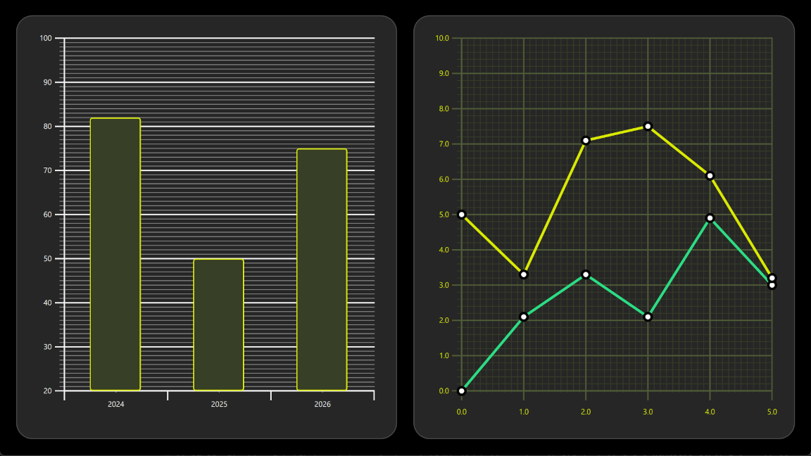
以下のセクションでは、BarSeries を使用した棒グラフの作成方法と、LineSeries を使用した折れ線グラフの作成方法について説明します。
例の動作確認
サンプルを実行するには、次の手順に従ってください。
- Qt Creator
Welcome モードを開き、Examples からこのサンプルを選択します。詳細については、Qt Creator の「チュートリアル:ビルドと実行」を参照してください。
- Qt Extension for Visual Studio Code
Command Palette からQt: Open Qt examples コマンドを実行し、リストからこの例を選択します。詳細については、Qt Extension for Visual Studio Code の「チュートリアル:ビルドと実行」を参照してください。
BarGraph
この例の最初のグラフは棒グラフです。作成するには、まずGraphsView コンポーネントを作成し、X axis 、Y axis 、theme を設定します。X軸は3つのカテゴリを持つBarCategoryAxis です。垂直グリッドと軸線は非表示になっています。Y軸は、20から100までの範囲が表示されるValueAxis です。tickInterval を使用して、10値ごとにラベル付きの主要目盛が表示されます。subTickCount 9 を使用して、1値ごとに副目盛が表示されます。つまり、主要目盛の間に9つの副目盛が配置されます。最後に、暗い背景に適したtheme が追加されます。このテーマは、グラフの背景グリッド、軸線、およびラベルを調整します。
GraphsView {
    anchors.fill: parent
    anchors.margins: 16
    axisX: BarCategoryAxis {
        categories: [2024, 2025, 2026]
        gridVisible: false
        subGridVisible: false
    }
    axisY: ValueAxis {
        min: 20
        max: 100
        tickInterval: 10
        subTickCount: 9
    }
    theme: GraphsTheme {
        colorScheme: GraphsTheme.ColorScheme.Dark
        theme: GraphsTheme.Theme.QtGreen
    }
...これを棒グラフにするには、BarSeries を追加します。
BarSeries {
...次に、BarSet を使用して、BarSeries にデータを追加します。3つの棒があり、棒の色と境界線のプロパティがカスタムで定義されています。これらのプロパティは、GraphsTheme に設定されているseriesColors を上書きします。
BarSet {
    values: [82, 50, 75]
    borderWidth: 2
    color: "#373F26"
    borderColor: "#DBEB00"
}
折れ線グラフ
この例の2つ目のグラフは折れ線グラフです。こちらもまずGraphsView 要素を定義することから始まります。独自の外観を得るために、カスタムGraphsTheme が作成されます。GraphsTheme は、背景グリッドや軸に対して非常に幅広いカスタマイズ機能を提供しており、これらはtheme の設定よりも優先して適用されます。
GraphsView は、このグラフに適したaxisX およびaxisY を定義します。
GraphsView {
    anchors.fill: parent
    anchors.margins: 16
    theme: GraphsTheme {
        readonly property color c1: "#DBEB00"
        readonly property color c2: "#373F26"
        readonly property color c3: Qt.lighter(c2, 1.5)
        colorScheme: GraphsTheme.ColorScheme.Dark
        seriesColors: ["#2CDE85", "#DBEB00"]
        grid.mainColor: c3
        grid.subColor: c2
        axisX.mainColor: c3
        axisY.mainColor: c3
        axisX.subColor: c2
        axisY.subColor: c2
        axisX.labelTextColor: c1
        axisY.labelTextColor: c1
    }
    axisX: ValueAxis {
        max: 5
        tickInterval: 1
        subTickCount: 9
        labelDecimals: 1
    }
    axisY: ValueAxis {
        max: 10
        tickInterval: 1
        subTickCount: 4
        labelDecimals: 1
    }
...データポイントを可視化するには、カスタムDelegate コンポーネントが使用されます。
component Marker : Rectangle {
    width: 16
    height: 16
    color: "#ffffff"
    radius: width * 0.5
    border.width: 4
    border.color: "#000000"
}これを折れ線グラフにするには、LineSeries を追加します。これにより、pointDelegate が、先ほど作成したカスタムDelegate コンポーネントを使用するように設定されます。データポイントは、XYPoint 要素を使用して追加されます。
LineSeries {
    id: lineSeries1
    width: 4
    pointDelegate: Marker { }
    XYPoint { x: 0; y: 0 }
    XYPoint { x: 1; y: 2.1 }
    XYPoint { x: 2; y: 3.3 }
    XYPoint { x: 3; y: 2.1 }
    XYPoint { x: 4; y: 4.9 }
    XYPoint { x: 5; y: 3.0 }
}2番目の線系列も1番目と同様です。これはGraphsView 内の2番目のLineSeries であるため、seriesColors から2番目の色が自動的に選択されます。
© 2026 The Qt Company Ltd. Documentation contributions included herein are the copyrights of their respective owners. The documentation provided herein is licensed under the terms of the GNU Free Documentation License version 1.3 as published by the Free Software Foundation. Qt and respective logos are trademarks of The Qt Company Ltd. in Finland and/or other countries worldwide. All other trademarks are property of their respective owners.
